I wish this was a more “detailed” report, but very much like the work on the big 1/96 scale Apollo/Saturn V Launch Umbilical Tower, I started the documentation phase too late into the build for that. The instructions provided by David Maier are very finely detailed, and need no embellishment or interpretation. As I did in the LUT article, I would emphasize to READ THE INSTRUCTIONS prior to beginning the work and prior to each assembly phase, so you are aware of the pacing and context of the total build at any given time.
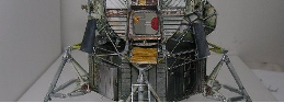
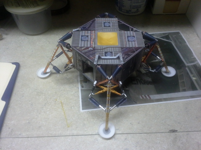
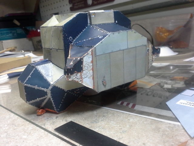
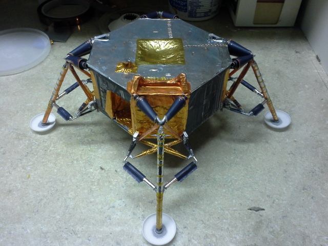
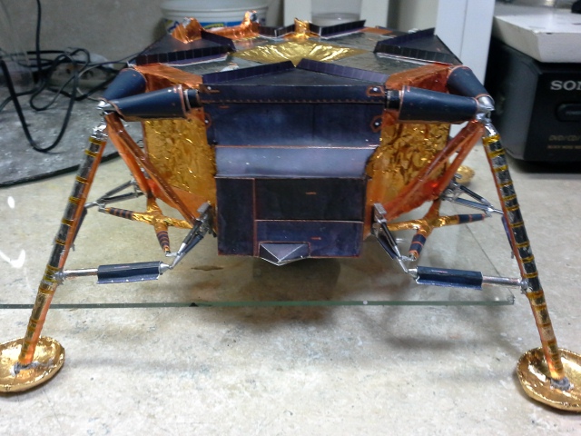
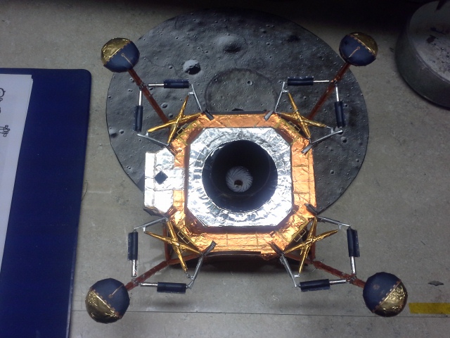
Here's a photo of the prototype model as David Maier of Edu-Craft was completing the build at the "primary structural" level - before foil insulation was added.
Here is where my “two cents” come in.
Again, as with the LUT model before, I find that my ability to roll proper looking paper tubes, repeatedly, is quite limited. For the LUT, assembly parts like the round Truss Girders that angle from each level up to the central anchor point were my downfall. I fixed that problem using pre-made paper tubing and drinking straws of the the proper diameters.
Here, things are different and “matters are worse.” There are a slug of finely detailed, intricate assemblies which must look good in order for the model to have the desired finished appearance. So while I knew I could get some of these things done, it was not something I looked forward to, and chose to look for “alternatives.”
The source for those alternatives proved to be Shapeways.com – the 3D printing store on the Internet. Mr. Vincent Meens, whose 1/24 scale scratch-built LM-5 model, built to realize the exquisite LM drawings of John Ortman, has become legendary, has now opened a presence on Shapeways which offers 1/48, 1/32, 1/24 and 1/16 (!) scale LM parts for sale. Yes, that’s right – 1/16 scale. (The price for any of the 1/16 structural parts is “insane”) Nevertheless, the cost for many of the 1/32 scale detail parts is quite realistic, and provided an alternative source for those of us without the extreme dexterity needed to hand-fabricate these parts.
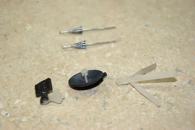
The areas I chose to buy as 3D printed parts for are shown below. These parts all came from Vincent Meens' former Shapeways.com webstore - "Space Models."
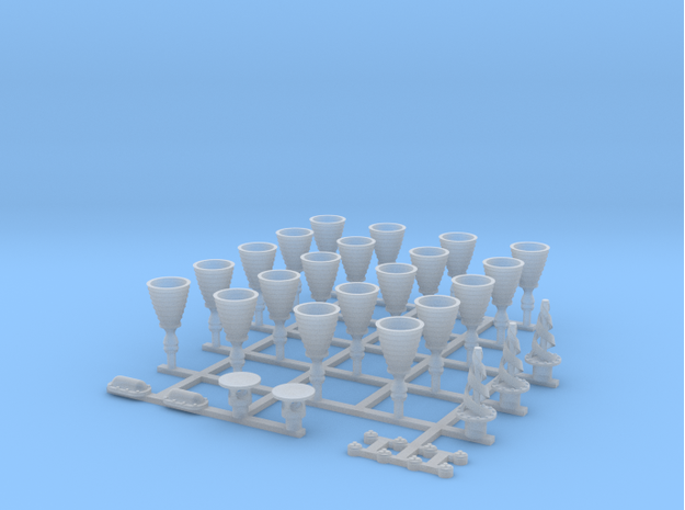
The parts bundle called the “Detail Pack” found in the 1/32 scale Ascent Stage parts list. They include the Reation Control Sysyem thrusters, Aft Structure vents, the small “cork-screw” shaped Omni Antennas, the front-mounted Acquisition Lights and a pair each of the cabin vent cover and the rear section access cover.
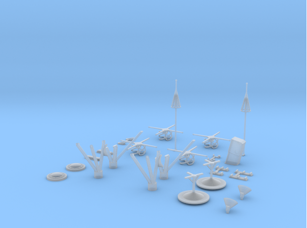
Another Detail Pack provided the upper Omni Antennas and their supports, the EVA Antenna(s), the front-mounted Rendezvous Beacon Len(s), Docking Target(s), the The Main Umbilical and the external portion for the optical telescope.
After looking at the fabrication of the two engine bells, I also decided to get both the Ascent and Decent Engines from Meens' Shapeways store.
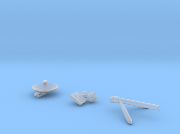
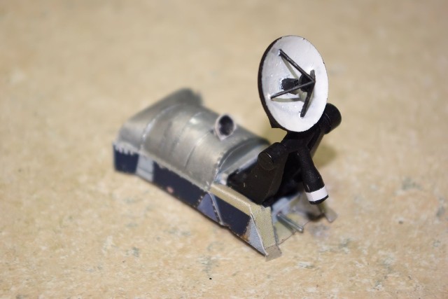
I also ordered both the S-Band Steerable Antenna complex as well as the Rendezvous Radar antenna from Shapeways.
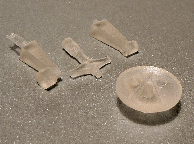
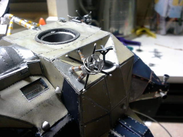
As the build has progressed through the installation of the LM interior into the Forward and Aft Sections, the fabrication of the radar was part of this sequence. We’ve already integrated the Meens' Shapeways parts into this element of the Edu-Craft build with good success.
I was able to put together the lower part of the antenna mounting supports, which formed a short “pocket” that sets into the upper Gyroscope Housing. Then, I placed the Meens 3D printed supports onto the glue-filled upper surface of the lower mount and cemented them into place, using the antenna pivot boom installed for proper alignment. The results can be seen here. Looks quite good.
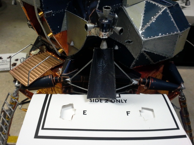
The Optical Telescope tube that goes into the Gyro Housing and the Docking Drogue which goes into the Tunnel actually came out good, so they were used “as provided” by Edu-Craft and can be seen in its respective location.
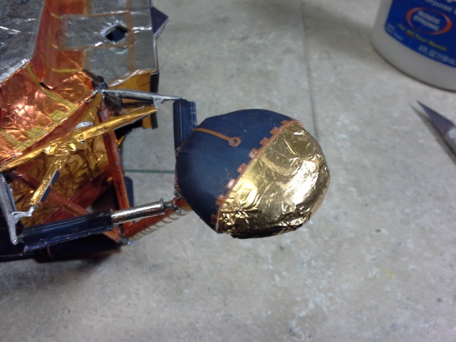
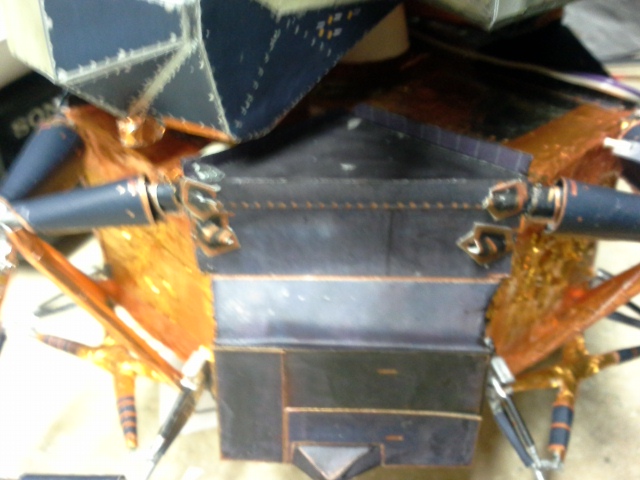
The Ascent Engine has also been “hybridized,” using the Edu-Craft manifold housing onto of the Meens-Shapeways Ascent Engine Bell. Although the white exterior of the plastic bell is “correct” in terms of color, there needs to be a coat of Flat White placed over it to create a smooth finish. I used Testor’s Metallizer “Burnt Metal” to do the bell’s interior.
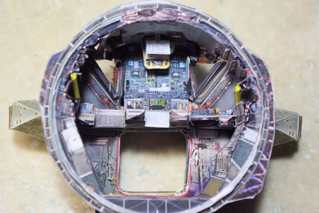
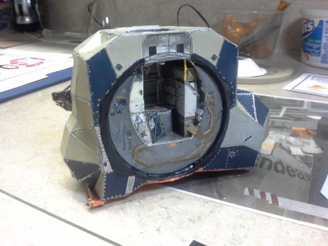
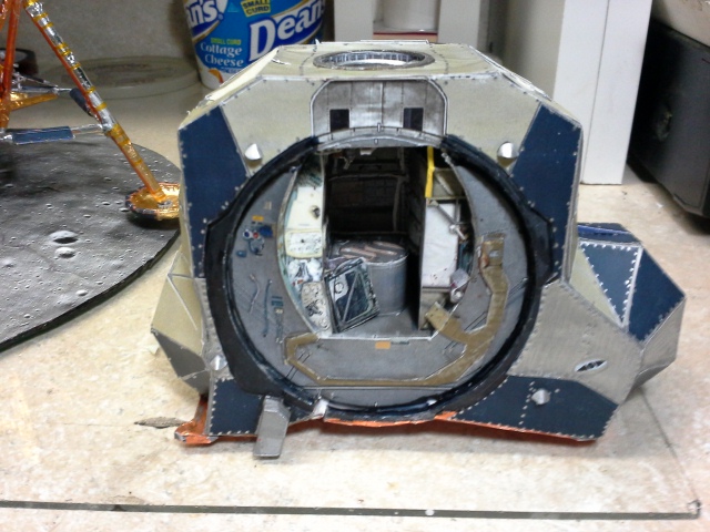
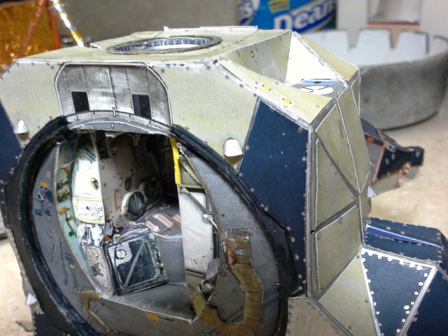
This photo shows the interior of the Ascent stage looking aft and up. The LM hatch is secured in place. Relief detail includes the purge valve, hatch handle and raised hatch structure.
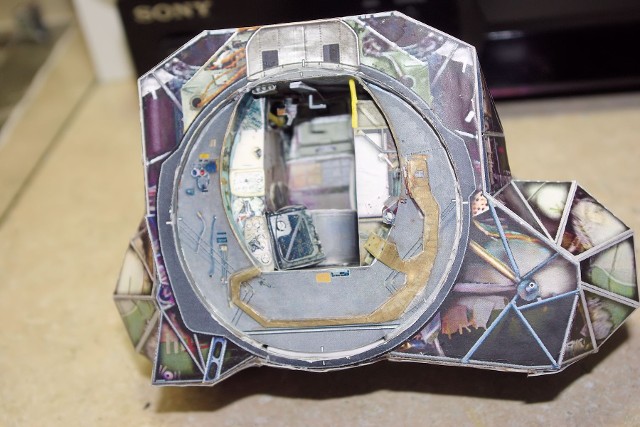
The LM aft interior also includes the environmental system controls and the racks for the PLSS units stored for EVA.
I’ve decided that after completing the major painting of the S-Band Steerable antenna, and the two Omni Antennas, I would leave the foil & tape covering until the point where the antenna would be actually installed onto the model. These steps are going to be very time-consuming, and the wraps could be damaged during interim handling. So, they go back into the Zip-Locks until further notice.
The Meens-Shapeways Detail Set also provided two copies of the Rendezvous Beacon, which mounts on the front of the LM’s “nose.” There is a fair amount of detail “printed” into the part, so we took our time to paint both copies, to see which one turned out best. The main ring is Flat White, with the retainer ring for the lens painted Aluminum. I left the center part “unpainted,” including from the back, as the placement of the lens over the nose of the model should provide a sense of depth behind the lens that will look quite realistic.
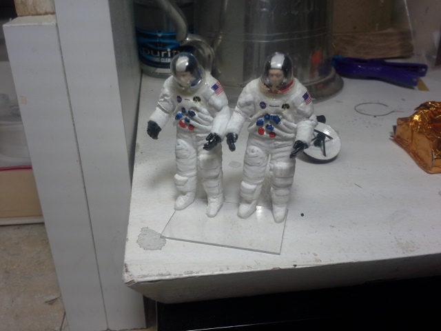
The two standing “crew-members” provided by Edu-Craft are formidable to build, at least from my perspective. I tried assembling the LMP figure and found the results were just not going to be at a level that I would be happy with. I do agree, however, that having the crew standing at their location in the Forward Section is a good idea. The trick is now to find appropriate-looking 1/32 scale Apollo Astronaut figures…
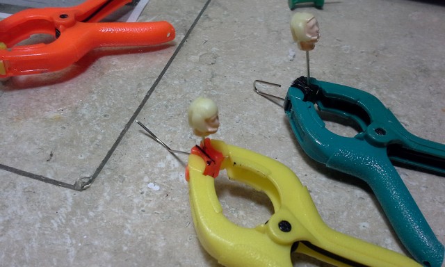
The answer may lie in the “hybridizing” of two sets of 1/32 scale astronaut figures – one offered as lunar EVA figure, in the Max Grueter “Figurative Studies” shop on Shapeways.com, combined with the heads and bubble helmets from the New Ware 1/32 scale Apollo CM Crew. The New Ware detail kit has been around for some time, and I used them in the renovation of the 1/32 scale Monogram CSM in an earlier article. But, taking the New Ware crew from “seated” to “standing” would require a lot of cutting, filling and shaping. When I found the Max Grueter figure, it appeared to me to be far easier to remove the AL-7 EVA helmet from that figure, as well as the PLSS unit, and place the New Ware crew heads and bubble helmets on top.
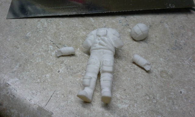
Cutting away the PLSS (backpack) was not easy. The plastic material used in 3D printing is very dense, and does not cut readily. Therefore, a razor saw and some degree of patience was required. The front-pack camera was also removed, as well as the helmet (and head!). The arms were cut at an angle, just below the elbow. The boots were also trimmed down later, as the crew did not wear their EVA boots during the majority of the flight.
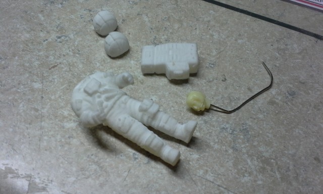
The arms were filed down to increase the angle and ACC'd back into place. Because the ACC did not "latch" immediately to this plastic, I found I needed to reinforce the joint during the curing time, so a hole was drilled into the arm segment, and then into the shoulder section, and a short piece of paper-clip wire was inserted in order to get strength and stability. I also used a paper clip to support the New Ware crew head for painting and detailing.
The head detailing starts with the primary face color, and then follows the guidance provided with the New Ware instructions.
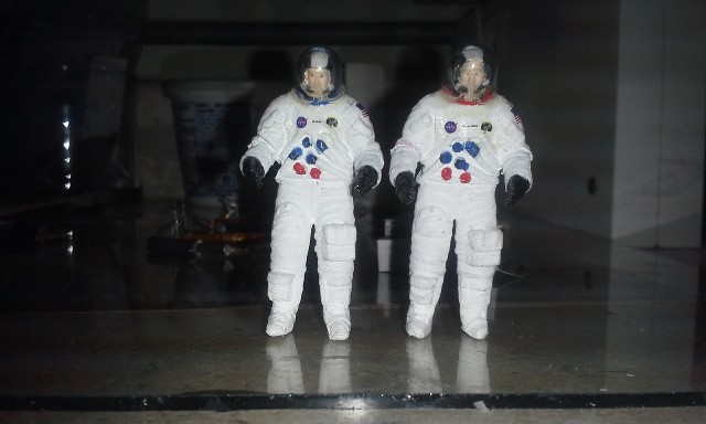
The results are these two guys, who will eventually be standing at the helm of LM-5. Today, Max Grueter offers 1/32 scale LM Pilot figures, ready to 3D print.
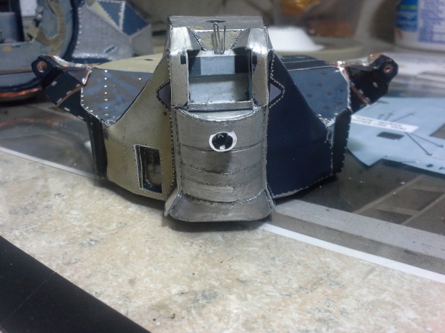
Now, it’s was time to begin fabrication of the Descent Stage. The plan is to first cut-out the various templates, attach a series of them to the substructure material and press them flat until the glue fully cures. Then the inner skin went onto the bottom main plate and pressed flat until dry.
We also finished construction the MESA (modular equipment storage assembly) prior to our room re-modeling break.
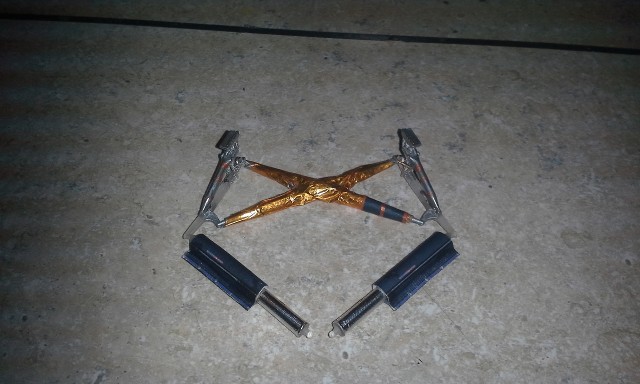
While the framework of the Descent Stage was setting up, we started working on the Landing Gear lower strut assemblies. The goal was to use the Shapeways-Meens 3D printed parts, but to cover them and detail them the way David prescribed in his instructions. Here, the lower assembly is sporting foil covering, the Strut 2 marker and the formed paper cylinder covers around the front elements.
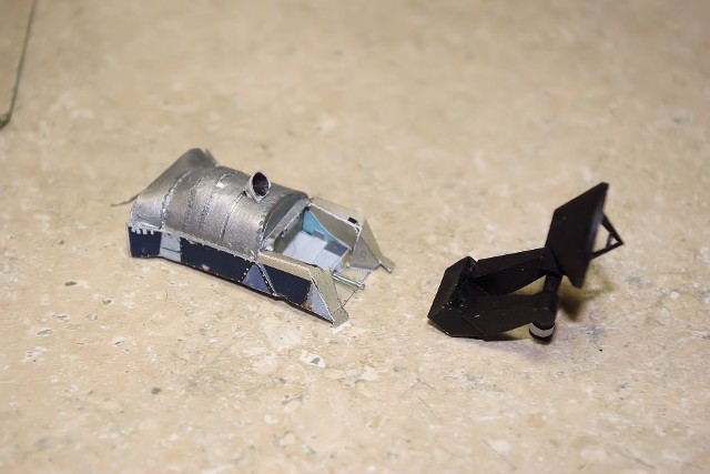
Here, I integrated the Shapeways-Meens 3D printed Descent Engine Bell with the Edu-Craft thrust chamber and internal assemblies.
The internal view shows the Ablative Shield and thrust chamber interior, just as David wanted it to look. This assembly will be fitted into the engine power-head later.
We reached the point where we were "adapting" the Edu-Craft instructions. To account for the presence of the 3D printed parts, much of the instructions used to do the physical fabrication of that part could be overlooked. The coverings, however, are still one of the interfaces between the 3D part and the final look on the model.
Once I got into the process of covering the landing gear struts and outriggers with the proper colored foils, I did not take many photos of the process while "in work." But, let's take a look at how the process played out.
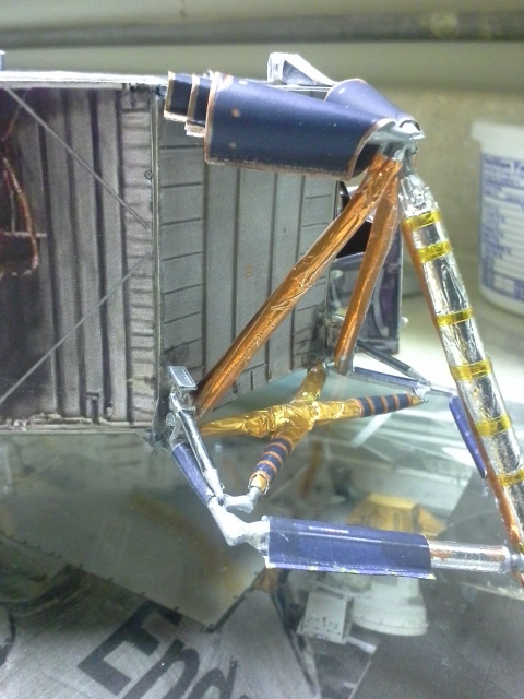
The gear assembly consists of three major units - The lower cross-members, the outriggers and the main gear strut. After placing the foil and paper covers over the lower cross-member assembly, it was secured onto the lower edge of the Descent Stage appropriate to the location. I had also previously attached the gear channels to the location on the bottom of the stage, so these played a part in locating the position for the cross-member attachment.
One note on the Shapeways-Meens 3D printed parts - They are somewhat delicate, so care must be taken in handling, during the covering and foiling procedures.The detail to be found in these parts is phenomenal,but this also makes them prone to breakage, especially at the very detailed joints. Please be careful! This is one area where the wire & paper parts of the standard Edu-Craft build would likely be more "forgiving." But, the finished look of these parts is pretty cool...
The tape lines on the main gear strut were placed after application of all foil sections onto the strut and were made from cut-down strips of actual Kapton tape, and not using the metallic pen solution provided by Edu-Craft. While the copper-colored metallic pen worked fine on a number of other locations specified, I felt the use of real Kapton tape strips would look more correct here, and the application could be done prior to assembling the strut to the rest of the gear system.

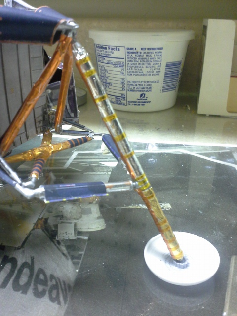
After placing the cross-members and letting them set in place, the outriggers were added by scribing a hole into the upper edge mounting location, as would also have been used by the Edu-Craft part, and set the two upper location into place. Once set, the lower locations were set at the focus of the rear cross-member/stage panel interface. The 3D printed top tip of the main gear strut "snaps" into position into the capture location on the upper outrigger set, and then the two ball joints of the cross-member engage into sockets on the rear-side of the strut. After all four gear were installed, the Landing Pads were set onto the ball-equipped lower tips of the main strut.
 The forward-facing gear (Gear #1) has integral fitting at the top to attach the ladder to.
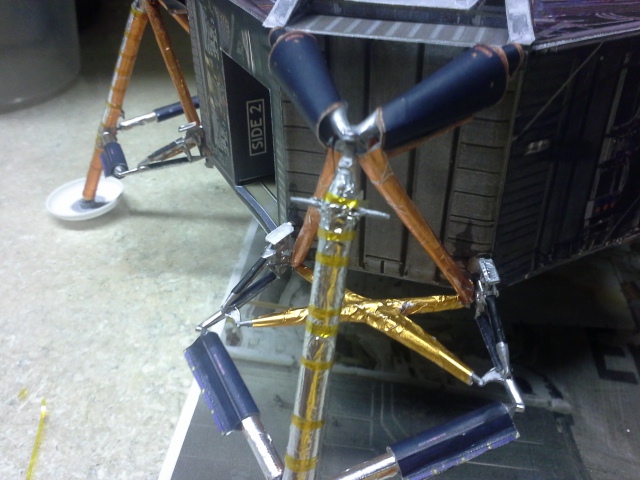
At this point, the Attach Points for the Ascent Stage were placed onto the top surface of the Descent Stage. My one "fatal flaw" thus far in this build was the use of wooden dowel rods in place of the wound paper tubes originally assigned to these locations. Come to find out, you are supposed to use toothpicks as securment pins, emanating from the Ascent Stage that would have gone through the tubes and support the two sections together and in alignment. Now, I will need to find an alternative to that mode of attachment. I think the use of plastic tubes and rods, immediately behind these original points - this might work.
On the other hand, I may not choose to have the Ascent Stage be removable from the Descent Stage. That is also bound up in the decision to "illuminate" the Ascent Stage's interior with white LEDs. The wiring for those will need to run "somewhere."
So, the decision on how to, or if I even need to do other penetrations into the Descent Stage can be deferred until we decide our final build configuration.
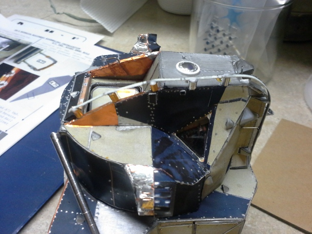
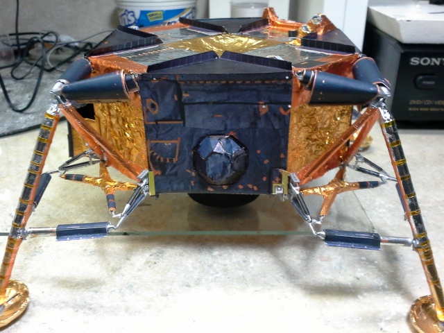
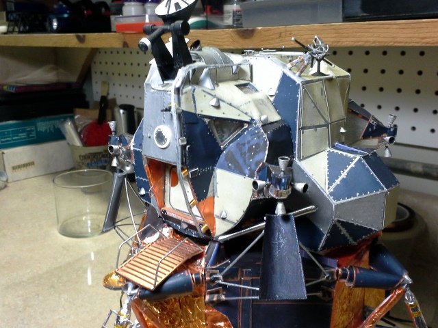
In the interim, we've begun the process of applying the external covering panels to the sides of the Ascent Stage. We are following David's instructions to the letter, in order to get the desired look.
This shows the left side to the stage, without panels applied as of yet. We have, however, done the "additional" application of silver pen to all of the framing lines of the side, so that any exposed frame will look like metal.
The left side with all coverings installed.
Here is the right-side of the stage with all covers in place. We will proceed to the aft section, along with the upper surface around the docking tunnel.
Here are both the rear and front sections of the Ascent Stage with all external thermal covers attached.

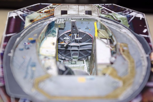
The two LM crewmen were affixed to a sheet of thin clear acrylic for locating and stabilizing. The acrylic plate locates directly over the floor of the cockpit.
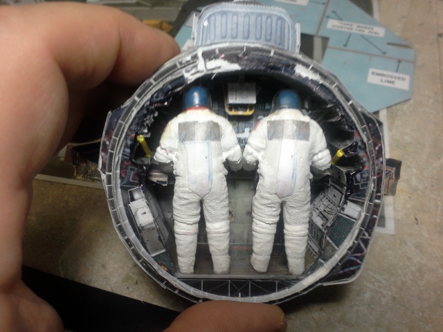
We are thinking about a way to illuminate the LM cockpit interior, and the space between the two standing crewmen looks like an opportune location.
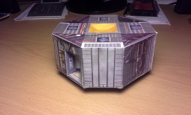
We began the process of placing the thermal covers onto the surfaces of the Descent Stage, as per the Edu-Craft instructions. Our choice of placing the 3D-printed landing gear so soon in the build had an adverse effect, as it makes placing the foil panels more difficult. But, with a little extra trimming, and moving the panel sideways through the outriggers, we managed to get all four of the Rose Gold end covers into place.
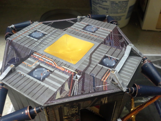
Next, it was time to place the primary silver foil plate onto the upper surface of the Descent Stage. The patterns for all of these foil panels comes from the paper sheets of the model and are traced or cut directly (your choice) from the correct color of foil. For this large upper section, we used heavy-duty aluminum foil, traced to pattern and cut out. The surface was "tinted" using the Blue Sharpie highlight marker, as recommended by Edu-Craft. The result is better than I had thought, and you can really see the blue tint. It simulates the transparent blue cover sheet that was part of the nickel-foil element used on LM-5.
Next, the gold foil center section was installed, along with the Umbilical thermal cover, the "tube" of foiled seen on the left side. Then, we started the process of placing the copper foil sections onto the outer edges of the four end quadrants. Again, because the gear is already on the model, we had to take the section apart and install it around the gear struts. The forward "overhang" section went on first, then the top surfaces and covering for the Ascent Stage attach points. Copper and Gold pens marks are used to highlight tape locations, as per Edu-Craft directions.
It was also at this juncture that the lower plumbing cover was thermally-covered with copper foil, as per the Edu-Craft instructions. This application takes the foils right to the cone-shaped opening for the Descent Engine heat shield.
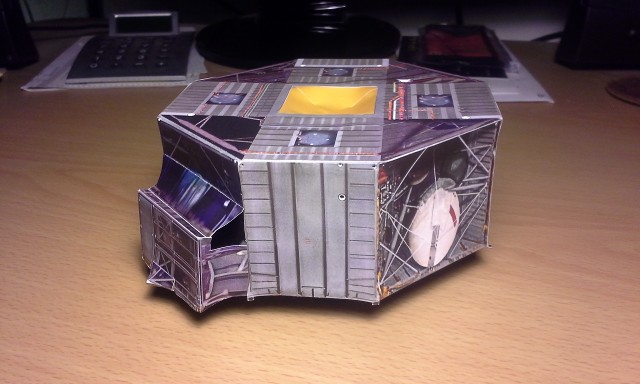
In order to application, the four large quadrants of the Descent Stage were covered with the black paper "foil-like" coverings provided in the kit. This is Side 4, with its tank cover pre-installed into the opening in the main cover, then located onto the side. Note the two ridges on the upper edges of the panel, which were always part of the LM's construction, but until working on this model, were not know even to myself.
This is the ALSEP covering on Side 6. It is composed of three black elements and four gold foil coverings, applied in sequence around the ALSEP packing. All tape lines were done with fine copper/bronze ink prior to installation.
This is Side 2, which includes the MESA. The MESA has been previously set into position with its lower hinge panel glued to the lower interior edge of the opening, after application of the gold foil covers. There are three black panels which are part of the system, and one application to the MESA itself.
Side 8 has a Rose Gold cover applied over the S-Band antenna "bulge", which is placed onto the front left surface of the side before the foil goes down. Then, the system of four black panels is applied over the foil.
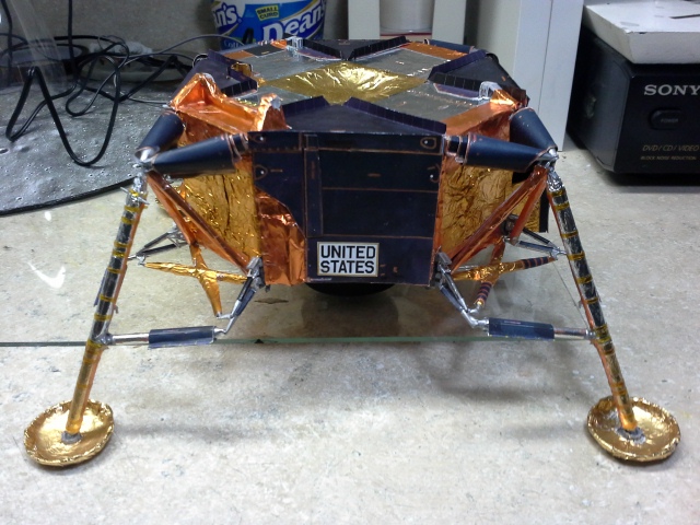
The "United States" placard was "formed" and then applied to the outer surface, in order to achieve the greatest degree of realism.
The four "anti-glare" covers were then applied to the inner portions of the gold-foil covered footpads. As these are printed paper, care must be taken to brash a full coating of white glue over the entire back surface, in order to soften the paper for forming. Once brushed on, let the glue soak in for about 40 seconds or so, then you can place the cover onto he pad, aligning it with the central axis of the pad, and slowing wrapping the cover over the pad surface and then crimping the edge over the pad's upper edge.
Remember, the cover for the gear on Side 1, the forward leg, does not have a landing probe location.
After embossing the provided patterns into the silver foil surfaces of the Descent Engine Heat Shield, they were applied to the Part D48 inner sub-support surfaces and then to the lower plumbing cover surface, to close out the installation of the Descent Engine system into the stage. The last sliver foil panel to be installed was the covering on the bottom of the ALSEP container, seen on the left side of the photo.
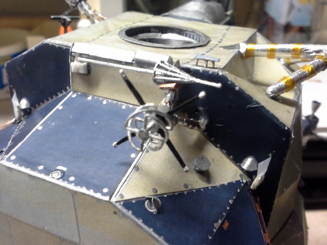
After that, we set about the task of cutting out, forming and applying all 21 of the Ascent Stage Vent Covers. These were "reverse colored" in silver ink quite a while ago and set aside until this point. One cut out, they are formed easily by placing the cover "face-down" on the fingertip, and pressing down with a pencil point along the long axis of the cover. This causes it to "roll" inward, creating the shape needed. They are then set onto the marked "crescents" over each of the marked locations. Care must be taken to note which direction the crescent "opens" to, as this indicates the orientation of each cover.
A close-up of the vent covers on the upper part of the stage.
Vent covers applied to the forward section. There are nine vent cover on this section alone. Also, the 3D printed Docking Beacon lens and the two Acquisition Lights on each side have been placed as well.
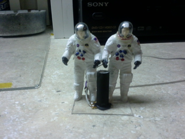
We took some "time out" to look at the possibility of interior lighting of the cockpit, as we are possibly faced with closure of the forward and aft sections of the Ascent Stage. Our attempt at achieving the "bayonet style" of capture between the sections has not worked out. Even if another locking method is applied, the idea of interior lighting is still interesting. We used a singe EZ-LED unit, left over from previous work, added a current-limiting resistor, and placed it onto the clear plastic support plate for the crew. Problem is, it was visible through the cracks in the Forward Hatch seam. So, we devised a "shade" made of white plastic tubing, and painted it Flat Black on 270 degrees.
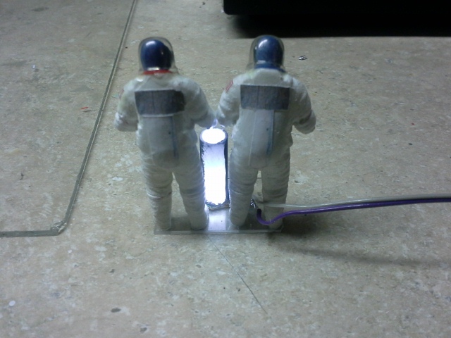
This allowed the light to leave upwards and back into the interior cavity.
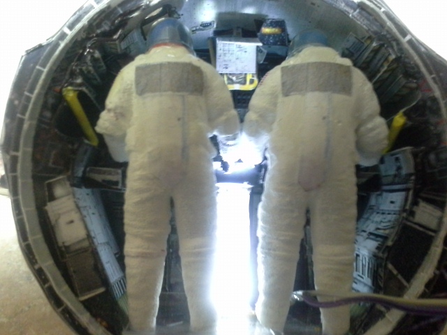
This was the test fit of the assembled system in the forward section. Notice the light hitting the upper surface of the cockpit, but not the front towards the hatch.
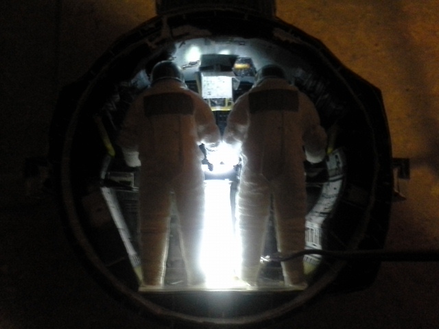
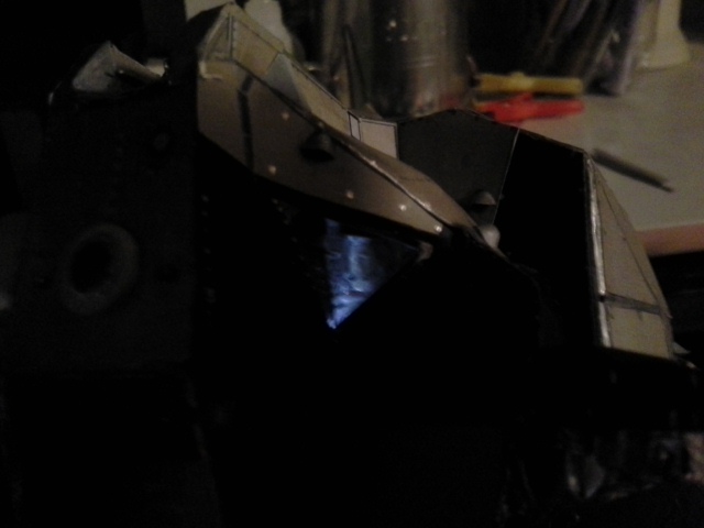
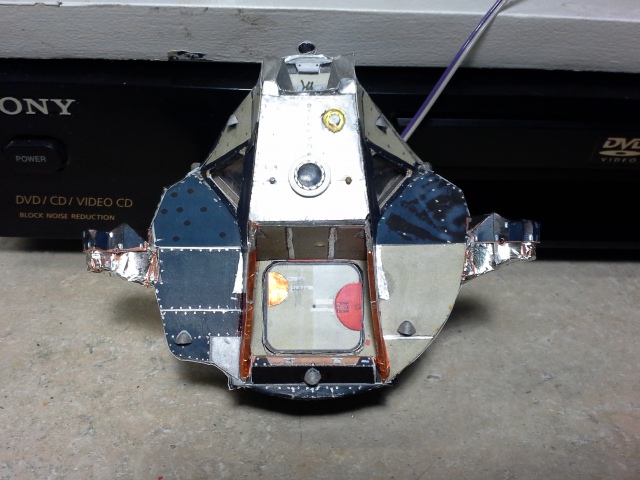
From the front, you can clearly see "Armstrong's" face in the LM's window. Clear, but softly lit. Exactly the effect I was after.
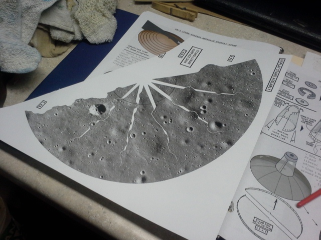
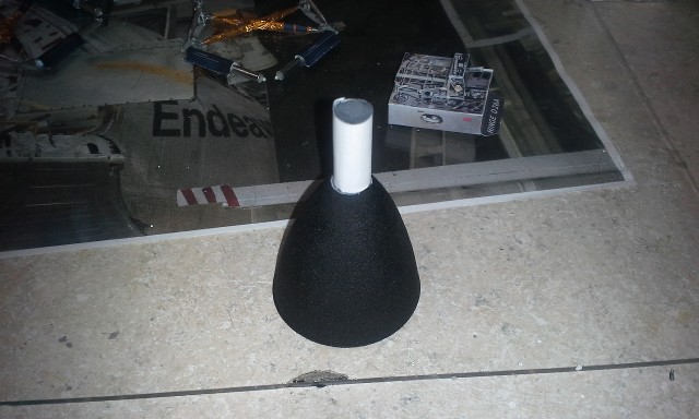
While on the subject of LED lighting, we also started to work on the display portion of the model, which will support the LM up high enough to keep the Landing Probes off the surface. The display base supplied with the model is the foundation. It is composed of nine circles of thick corrugated cardboard, sacked one on the other in successively smaller diameter, then pressed or shaved down on the edges to create a shallow dome. Over the dome, sections of paper are cut out and applied using heavy white glue to allow the paper to form.
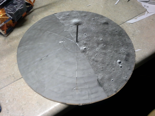
The frat layer is simple Grey. The second outer layer has lunar surface details printed in it. There are areas of each section which overlap onto the previous section, in order to create the illusion of continuous coverage. I used a single 10-penny mail as the central alignment tool.
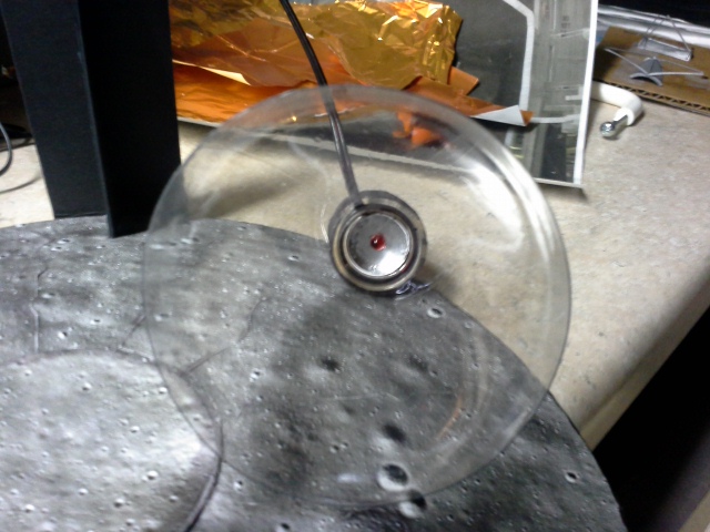
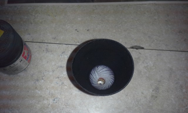
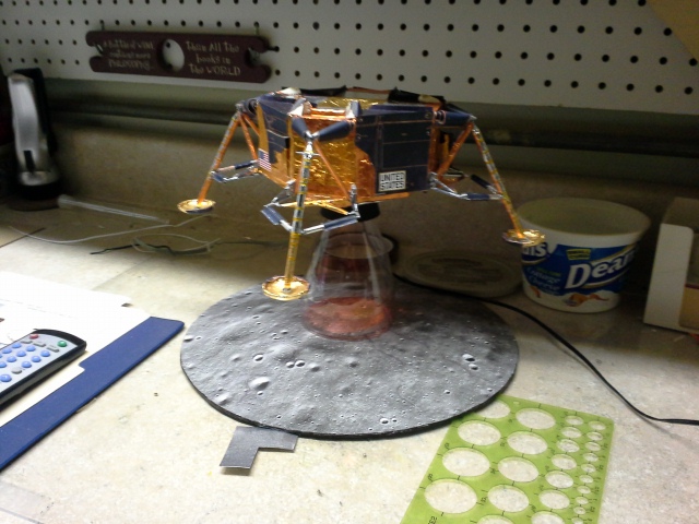
Edu-Craft's instructions call for a central post of silver-foil cover plastic to support the model, but I found if the integrity of the plastic bottle section was not compromised, there was no need for the post. This opened up the area under the support to look more like a "plume" from the engine. I used the "flicker LED" from a battery-powered LED tea-light as the source, created a fixture that inserted into the bottle's neck and this was the result.
More detail on this to come later.
We started placing the EVA Handrail along the port edge of the nose. Using pins as locators, and 2 mm long sections of 2.4 mm tubing wrapped with either copper or silver foil as off-sets, we started to place the folded paper handrail. The supports located on along the Gyro Housing lined up nicely, but the rail appears narrow with respect to the supports. I've decided to use one of the "contingency part" handrails, cut just a tiny-bit wider to lay over the current one and flush out the assembly. once that's set, the whole handrail get a coating of Silver metallic paint pen.
We also remedied the problem of "fixing" the Ascent Stage forward and aft sections, using a method employed in or Edu-Craft LM DSKY model. Sections of "threaded nails" like those used on RTA furniture were super-glued into specific locations on each interior side of the froward section, and matching receiver holes were placed into the forward wall of the aft section for them to engage into. Once location and fit were verified, the receiver holes were given a dose of super-glue, in order to reinforce the paper material at the interface.
Once the Ascent Stage problem was corrected, we verified that the locator pins placed into the stage interface points of the Descent Stage were still aligned with the holes on the Ascent Stage and set them together. With the Ascent Stage on, and the RCS quads in their final location, we could address the placement of the Plume Deflectors.
Our deflectors are "hybrids. using the Meens/Shapeways 3D printed deflectors, with the Edu-Craft printed "skins" contact cemented onto them. Unlike the Edu-Craft deflectors, whose supports are made of fairly rigid metal wire segments, the Meens/Shapeways deflector supports are very thin plastic, without sufficient "penetration" to remain locked into the locator holes placed on each major side. So, instead of putting the plume deflectors on first and then wrapping the supports with the printed paper "boots," I placed the boots onto the stage first, and used them as "sockets" into which the supports could be placed into and locked by cement.
A rubber cement bottle, with a folded piece of paper stock as a "shim" was used to correctly support and locate the deflector supports while the glue set. In this photo, you can also see the Meens/Shapeways 3D printed RCS nozzles in place.
Between here and previous photos, we also placed the Egress Ladder onto the forward landing leg, the Egress Porch onto the top of the forward gear, the Omni Antenna supports onto the front and back of the Ascent Stage and the Docking Target and Steerable S-Bank Antenna Support onto the top of the LM's Ascent Stage.
Here is the forward Omni Antenna located onto its support.
The aft Omni Antenna as well as the "stowed" EVA Antenna on the back of the Ascent Stage. The helium vents and their diffusers can be seen as well.
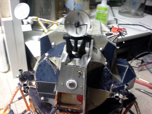
The Rendezvous Radar antenna complex is now fitted into the receptacle of the Gyro Housing.
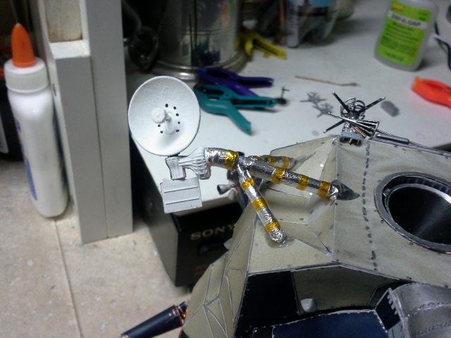
And, the Steerable S-Band Antenna now mounted onto the LM. As the 3D printed parts were designed more for "surface attachment" to another 3D printed plastic component, the locator holes specified by Edu-Craft did not apply. Therefore, we chose 5-minute epoxy to fix the antenna support in place, and then used silver foil to create the "boots" at the attachment points.

Here is a view of the hand-made LED housing I placed into the neck of the Trader Joe's Sparking Water bottle top Edu-Craft recommended to use to make the model support "plume." I did not re-work the neck of the bottle as the instructions showed, and used the threaded neck to hold the new cylindrical LED housing, with silver foil interior and a red "flicker LED" for illumination. The surfaces of the "plume" were brushed in straight lines with Clear Flat Acrylic in order to provide a very thin "texture" to the flame plume.
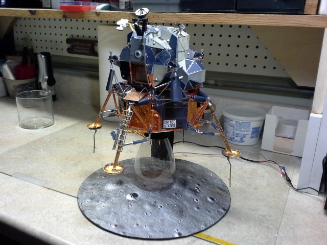
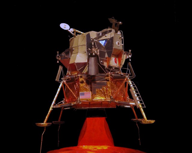
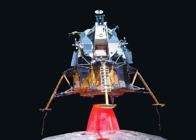
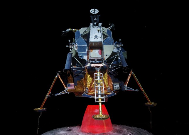
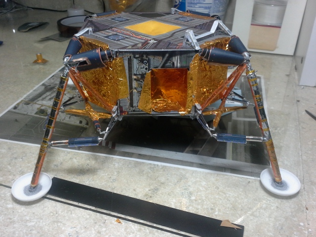
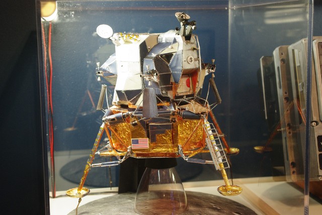
After all four RCS Plume Deflectors were installed, I inverted the Descent Stage and placed the Landing Probes on the three Landing Gear Pads they were intended to go on. Once those were in place, we put the Ascent Stage back on and placed the finished model onto our hybridized display base. Besides re-working the Support Plume and not using the central support tube, we also added an "umbilical" to the rear of the display disk, which would provide both support for and visual camouflage to the LED wiring of the plume LED and the cockpit LED.
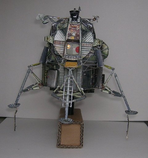
Even using the Meens/Shapeways 3D printed parts in lieu of the hand-made Edu-Craft versions, this was still one of the most challenging builds of any of the Edu-Craft products David has created. However, I think the results speak for themselves. The depth of visual detail provided in this kit is excellent, and the "roughness" of the exterior makes the model far more realistic looking than if it had normal injection-molded plastic construction.
Thank You, David Maier, for creating this kit and providing hours of challenging "fun" to space modelers once more.
Thanks also to Vincent Meens, whose work on Shapeways.com made the details of this model much better than I could have ever done by hand.
Here's a shot of LM-5's final display location.
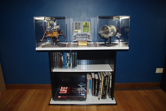
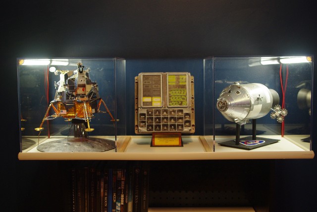
Sitting atop a new bookshelf I created specifically for this function. A five-sided 12" acrylic cube covers each of the 1/32 scale Apollo Spacecraft - The Edu-craft LM-5 on the left side and the Monogram CSM on the right. The Edu-Craft LM DSKY model sits amidship. The perimeter of the top shelf has edging that holds the cubes in place and the LED wiring exits on the outer rear corners for each display cube.
For the "grand view" of this new section of our home, please see the new "Lovely Apollo Room" Page of this website, by clicking here.