|
Manufacturer:
|
Monogram (originally), now under Revell. Kit is formally discontinued, but still availbe from eBay and other sources.
|
|
Cost:
|
Ranges from $27 to $40 and up, depending on source. Still availible for $32 from BuzzAldrin.com store
|
|
Scale/Size:
|
1/32 scale – 12.75 by 8.625 in. without display stand
|
|
Parts/Media:
|
Injection molded plastic, molded in colors or plated. New Ware parts were either resin or photo-etched (PE) brass.
|
|
Instructions:
|
Monogram instructions were good but basic. Recommended colors are not correct. Space in Minature Vol.6 has correct colors for spacecraft details. Those colors are indicated in this article.
|
|
Decals:
|
The Monogram decals were not used. New Ware decals used instead.
|
|
Paints/Supplies:
|
See article for paints used.
|
|
References:
|
New Ware detail set instructions; “Space in Miniature,” Vol. 6; NASA photos.
|
|
Molding/Casting Quality:
|
Overall, mold quality is good, A number of parts need re-fitting, shaping or modifications for accuracy.
|
|
Detail:
|
This kit has been the standard for the Block 2 Apollo Spacecraft in a large-scale model.
|
|
Accuracy:
|
The fundamental accuracy is good. New Ware detail parts make it better.
|
|
Fit:
|
Some fit issues. See article for detail.
|
|
Ease:
|
The standard kit, without significant change, is a relatively easy kit to build. A serious effort at accuracy changes it to a major undertaking, requiring significant patience.
|
|
Instructions:
|
The original instructions are OK. The paint schedule is not correct, as indicated in Space in Miniature.
|
|
Decals:
|
Original Monogram decals well made, but lack accuracy. New Ware decals much more accurate and require more skill to use properly.
|
|
Overall:
|
A good beginner kit “as is” and a firm foundation for the more adventurous space modeler to work from.
|
This build represents the second or third time I have built one of these kits. The most recent previous version can be seen in the “Real-Space Projects” section of LCSP. It looks pretty much as Monogram intended it to. I had accepted the gold color of the Command Module as “accurate” at the time and painted the clear plastic CM hull section in an attempt to match as closely as I could. The same went for the SM’s clear panel. The whole SM was painted silver and detailed. Both panels were left to be removable, as intended, to show the interior details. A little over a year ago, I added Space Modeling Systems decals to improve the overall detail.
For this new build, I had done more extensive research on the CSM system, incorporating many of the photos of actual CSM articles I have taken at both the Apollo-Saturn V Center at the Kennedy Space Center in Florida and the National Air & Space Museum in Washington, DC. As important as the photographic data was, additional research was needed to find out how these spacecraft “fit” into the history of the Apollo Program, and how their configurations may be similar to, or differ from, the vehicles that flew the lunar missions.
This is where Mike Mackowski’s “Space in Miniature” Volume 6 came into importance. This volume is dedicated to the Apollo Command and Service Modules, in both Block 1 and Block 2 versions and illustrates a number of the configuration differences between the CSMs as the program evolved.
The book points out that the CSM at KSC was originally intended for Apollo 18, which did not happen due to Congressional cut-backs, but was used as a backup for the manned Skylab flights. CSM119 was actually prepped for flight as a rescue craft when Skylab 2’s CSM began to show signs of potential systems failure in its Reaction Control System. The RCS problem was shown not to be systemic and isolated in nature, so the rescue flight was not flown. CSM119 remains at KSC, and is now the only “flight worthy” CSM artifact from the program.
The CSM105 at the NASM in Washington was used for anechoic testing early in the Block 2 phase of the program and is now mated to the backup Docking Adapter for the Apollo-Soyuz Test Program mission flown in July, 1975. Appropriately enough, it is on display with a full-scale Russian Soyuz craft, as flown on the ASTP mission.
Combining this photo data with other NASA photos, obtained via the Internet from various missions, data from the Apollo-Maniac’s website and John Duncan’s “Apollo-Saturn Reference Pages” website, we were armed with sufficient information to begin our quest, We’ve also gathered more data from other sources throughout the build on specific CSM systems and components. However, the build article included in Space in Miniature, Volume 6, written by Karl Dodenhoff, was ultimately the foundation for the build. Many thanks go out to both Karl and to Mike Mackowski for their hard work in providing this data to all space modelers, everywhere.
We also employed four products from New Ware on this build: The 1/32 scale Apollo CSM Exterior Detail Set (NW070), the 1/32 scale Apollo CM Interior Detail Set (NW002), the 1/32 scale Apollo Astronaut Figure Set (NW051) and the 1/32 scale Apollo CSM Decal Set (NW002M). The resin and photo-etched part sets provide the rich, accurate detail necessary to move the build into a far more realistic state, and reflect the best parts available for use on this model, in my humble estimation.
My build plans still included the ability to remove the panel sections as Monogram intended, even though I also intend to do the replication of the silver “Mylar tape strips” over the surface of the CM and the proper overall silver exterior color of the SM. Everyone else who has done this tape-pattern surface work have locked the CM panels together and filled in and sanded the seams before applying the strips of Bare Metal Foil© Ultra Bright Chrome for the tape effect. We will see how my “best intentions” turn out.
Service Module
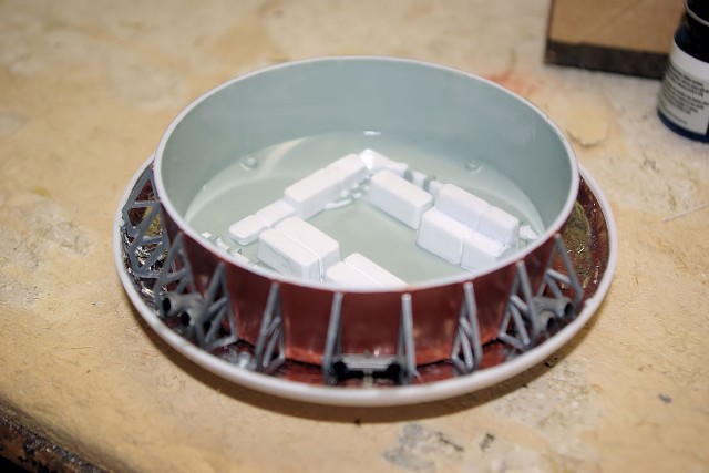
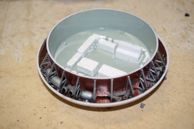
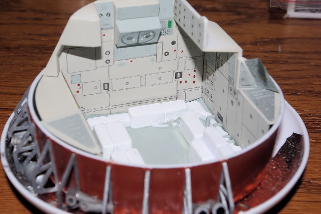
The SM consumed a large time of the early build, but much of the work could be done on the interior detail section prior to full integration. Working off of Karl’s article in SIM Volume 6 and NASA photos of the SM’s interior, all interior panel surfaces were first covered in silver foil to replicate the thermal insulation.
The liquid hydrogen tank was modified by adding the upper and lower wraps of corrugated styrene sheet, to add detail closer to the actual tank. The tank was painted in Chrome Silver. All electrical surface detail on the support shelf was done in dark gray.
The LOX tank shelf was built and painted as recommended by Karl’s article, as well as the revisions to the Service Propulsion System fuel tank.
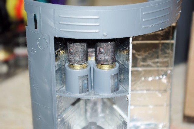
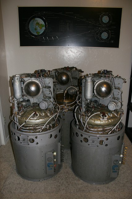
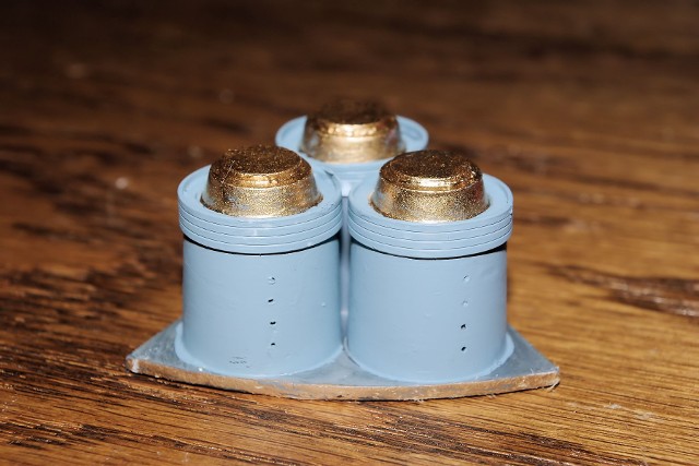
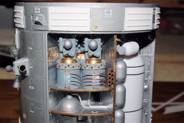
My original idea for improving the visible detail of the three fuel cells was to take photo images obtained of the actual fuel cells, print the required detail onto clear self-adhesive label stock and apply that to the bodies of the model’s fuel cells. While it looks better than just three “blank cylinders,” it just did not sat well enough with me to keep. So, we completely re-visited the fuel cells.
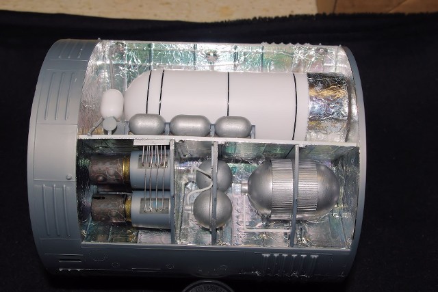
The original “first attempt” at the completed SM interior is shown here, with additional plumbing added to the tanks and wiring added to the fuel cells. I’ll provide more on the fuel cell subject later.
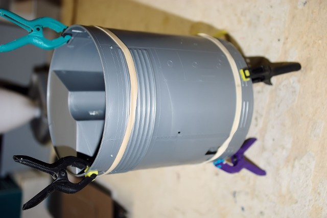
Along the way, the halves of the SM’s shell were cemented together. We used rubber bands to apply compressive pressure and clamps to hold the edges in better alignment, in an attempt to minimize the necessity of sanding and re-working the seams.
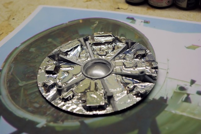
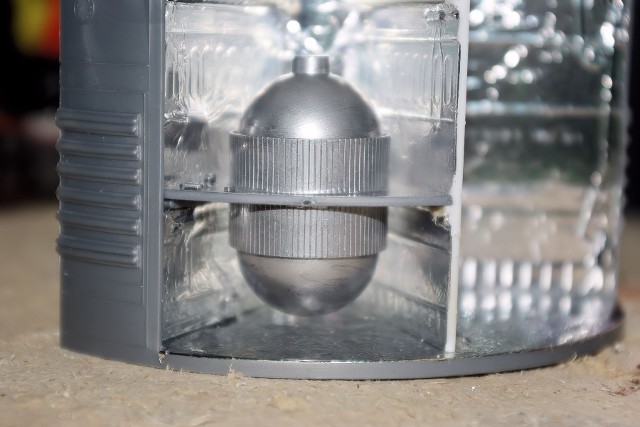
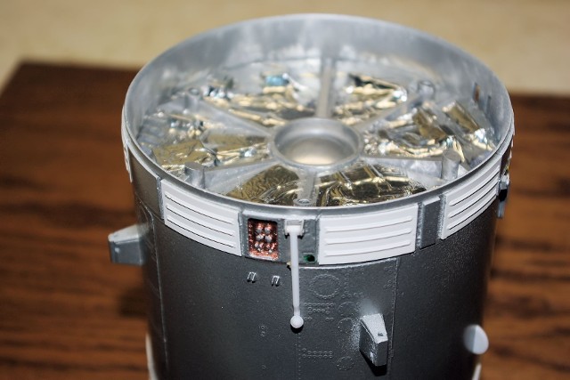
The forward bulkhead of the SM was clad with silver foil, while the CM support ribs were painted aluminum, and the central exposed helium tank dome was painted Chrome Silver.
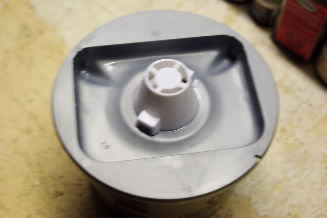
The SPS engine gimbal assembly was done on the aft bulkhead, so that the adhesives had plenty of time to cure and make the gimbal as robust as possible. Once cured, the externally-visible gimbal panels were painted with the mix of Insignia Yellow and International Orange required, achieving the proper color as indicated by Karl’s article and as seen in the NASM photos of the SM’s aft section.
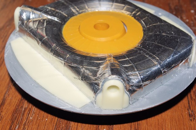
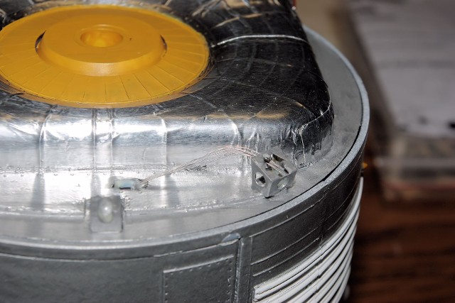
When the paint had dried, the tank dome section was covered with Bare Metal Foil to achieve the shiny, metallic surface quality seem in all SMs on display. Once the foil covering was done, I remembered that the molded-in SM umbilical connector elements had to be cut away so that the New Ware parts could be installed. Using a razor saw, I proceeded with this revision.
The opposite corner of the dome was also cut away by a span of 21 mm across, as indicated by New Ware and the new corner part installed. All of the New Ware flat resin elements were then placed onto the bulkhead dome, at their proper locations.
The resin high-gain antenna mount and its PE actuator part, along with the folded PE SLA Connector Housing were then fabricated and mounted to their locations on the bulkhead.
All “low” surfaces of the bulkhead exterior were painted aluminum. The back edges of the New Ware SM umbilical connector elements were painted Chrome Silver, to match the foil, while the edges were painted Rust and the lower flat surface was painted in a mix of white and Rust to approach the Salmon-like color seen on the actual spacecraft. The interior surface of the flat dome corner part was also done in Rust.
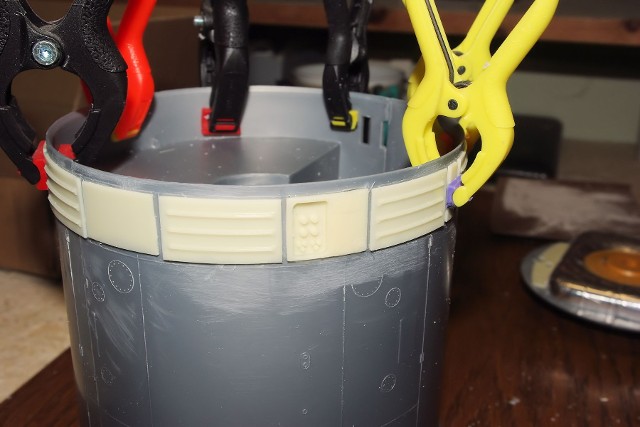
All of the molded-in surface radiator detail was sanded off of the upper edge of the SM, except for the indicators of division from one panel area to another. These lines were used to locate the applied New Ware parts. The resin EPS radiator panels and the associated separation panels were carefully cut away from their resin casting bases and sorted by part number. All of these panels are applied to the surface of the SM skin. The exception was the upper umbilical connector panel, which requires the use of a Dremel tool to cut out a section of plastic, allowing the “socket” portion of the part to fit properly. A word of caution here is to mark the area first and cut out carefully and slowly to prevent overcutting.
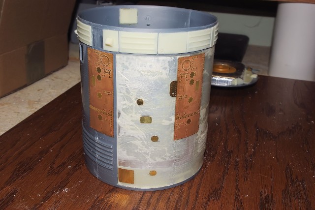
After completion of the forward panel application, the PE parts were applied to the sides of the SM, as indicated in the New Ware instructions. As this SM was to be of a mission prior to Apollo 15 (no SIM Bay), the layout for “Apollo 7 to 14” was used. As you can see, they add a great deal of surface detail to the model.
The pre-assembled plastic housings for the RCS “quads” had their PE detail panels attached to the four lower surfaces. After curing, the quad housings were attached to their respective locations on the PE detail panels of the SM.
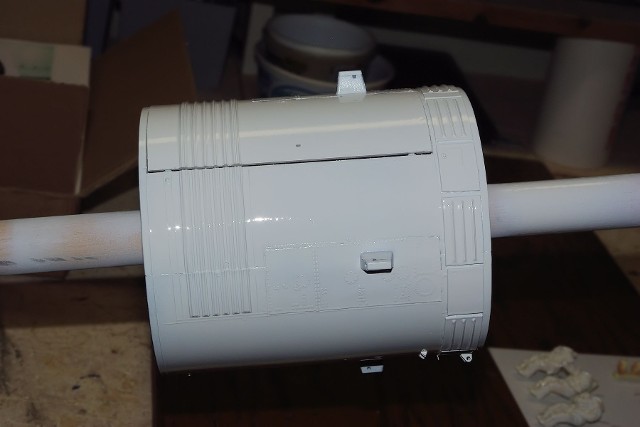
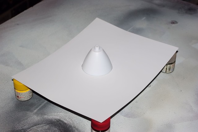
This major sub-assembly phase of the SM was then mounted to a 1-inch diameter wooden dowel-rod for rotisserie-like handling and the entire surface was sprayed Primer White. This would be the foundation for the SM’s silver color, and the final white color for the lower and upper radiator panels.
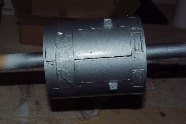
Once the primer had completely dried, the radiator panels were masked off and the silver SM final color coat was applied. The silver paint used was gloss-finish enamel, which would be a good surface for decal adhesion. The completed SM assembly will be “dull-coated” as a final step to protect the decals and seal the finish.
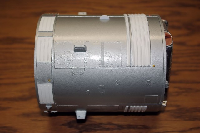
After drying, the masks were removed, silver and white touch-ups were done, and the silver separation lines of the lower radiator panels were painted in by hand.
All colored Acquisition Lights and Docking Lights were painted in accordance to the instruction provided by New Ware. The acquisition lights were done in Turn Signal Amber, Clear Red and Clear Green painted over the silver base, making for very good looking lights lenses.
At this point, the lower bulkhead was installed onto the SM body. After attempting to hand paint the SM umbilical connector head details in the interior of the connectors, I decided to try another route. I had taken a full-on photo of this area of the SM at KSC, so I took the photo, scaled it to match the opening, printed two copies onto white label stock, cut them out and inserted them into the openings, resulting in “photo accurate” detail, direct from a real SM on display in Florida.
Next, the forward bulkhead was installed into the SM body. The EVA Spotlight boom was installed into the New Ware folded PE mount, and the Umbilical Connector plate interior surface was painted copper to match the color seen in photographs. The “scimitar” antennas were also placed onto their locations on the SM body.
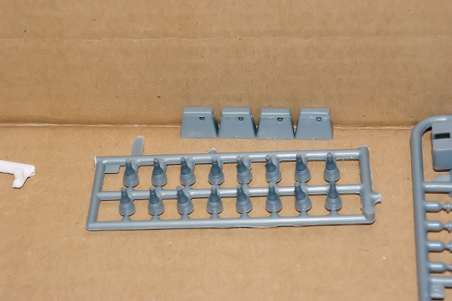
The RCS thrusters had their Gunship Gray throats painted while they were still on the molding sprue. After drying and removal from the sprue, the bells of the thrusters were painted with a mixture of Bright Brass and Chrome Silver, in order to achieve the yellowish-silver look of the real metals used. The thrusters were then located and secured into each of the four sockets provided on the housing.
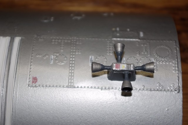
Using the New Ware manual for guidance, the SM marking decals were placed onto the module, including the plate markings which go on top of each of the RCS quad housings.
An additional piece of detail work was added, as recommended by the New Ware SM manual. A set of copper wire strands were added, running from the rectangular opening in the rear bulkhead resin plate of the SM to the SLA Connector, to simulate the cables which run from the spacecraft to this location. The strands were painted aluminum and locked into position with clear cement. Touch-up painting was done after the cement cured.
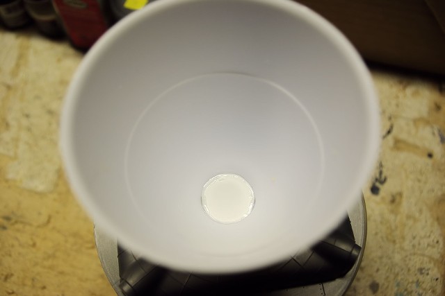
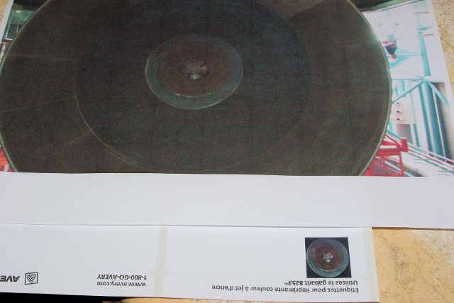
The Service Propulsion System (SPS) engine bell was examined early in the project as a candidate for receiving “photo-accurate” detail improvement. The bell’s molding contained three “bumps” on the flat interior bottom of the part – visually incorrect and a pain to try to get rid of, so we placed a simple styrene disk into the bell, over this location. The diameter of the styrene disk was the same as the scaled-down photograph I took of the very same location of the actual SPS engine throat and injector plate of CSM119 at KSC. This would be printed onto white label stock and placed onto the circle after the bell’s interior was painted.
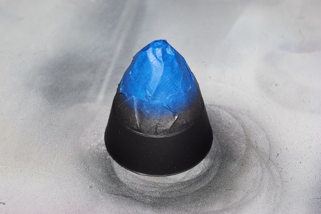
The bell’s exterior required the use of Testors Metallizing airbrush paints, using Burnt Metal for the upper section and Gun Metal for the lower section, as recommended in Karl’s article. I found these to be fairly temperamental and do not like contact with masking tape, even after the Metallizer Sealant was applied.
So, after repairing the lower section’s finish, I had to create a tight-fitting paper mask for the bell to slip into, right down to the divider ring molded on the outside of the bell. Then, I applied the Burnt Metal finish to the upper section. The results were quite good.
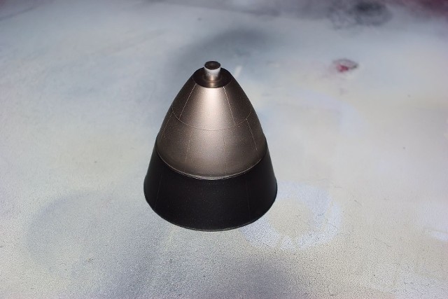
The engine bell’s interior was done in Flat Black, rather than trying to reproduce the panel-like interior of the lower section seen in the KSC spacecraft. I assumed that after an SPS engine was fired, there would be discoloration across the entire interior surface.
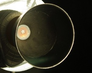
Even the label for the injection section was darkened slightly to work with the effect, and still promote a better sense of realism inside the engine.
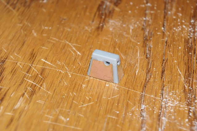
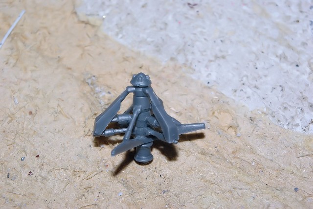
The SM’s High-Gain Antenna as originally provided in the kit is a decent-enough looking assembly, but lacks specific details from the actual article. This is where New Ware comes in. NW provides the resin parts and full instructions on how to improve the antenna support and horn assembly. Follow these instructions carefully, but they work as shown. The hinge point of the support arm is cut off and four new parts are added.
As for the PE parts for the four dishes and the “spiders” – the ten-legged internal supports - all of these parts are flat sheet metal. As finely detailed as they are, how to you make them rounded? Dish-like? Turns out, you have to be a little inventive and become a part-time metal worker.
In the auto industry, fender, hoods, etc. are formed from sheet metal using “stamping dies.” Large fixtures which form the metal are pressed into each other with immense hydraulic pressure, with the sheet metal in between. The instructions “show” placing the part between two elements to provide shape, but no other guidance is offered. Super. I don’t own any stamping equipment hardware. What do I do now?
Back in the “old days,” coach builders used to beat sheet metal into the shapes they wanted by using special hammers and either a bag filled with shot or sand to absorb the force and disburse it into the metal, heating and bending the metal with each impact.
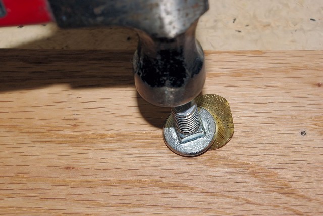
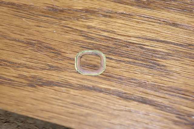
Out in my garage, I have some “carriage bolts” that were intended for the bumper of a car. These have large diameter, smooth, rounded heads. By placing the PE part between the head of the carriage bolt and a “pad” or form, I could shape the metal. I wanted a form plate of soft White Pine, but we didn’t have any, so I grabbed a scrap of ¾” Red Oak. Using a bench vise, I pressed the bolt head into the surface of the wood as much as possible, in order to impress the curved shape in the wood. Then, using a small hammer and placing the PE part over the curved depression, I struck the bolt with the hammer, and by moving the part slowly around, I got the shape I wanted. By God, it works!!
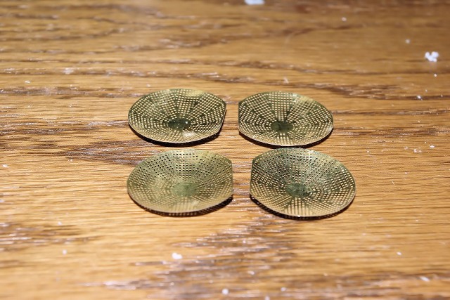
I used the same method with the spiders, too and they turned out just as well.
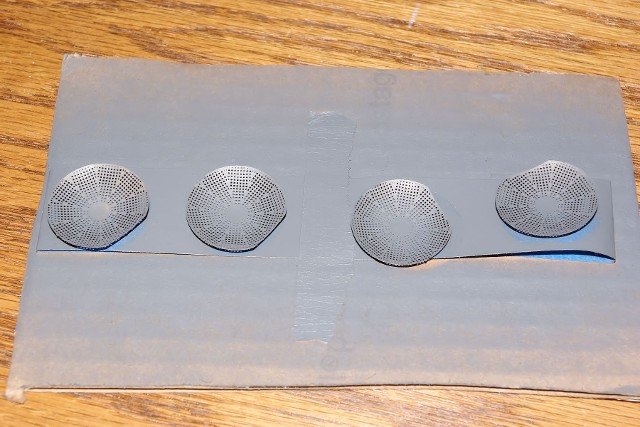
The formed dishes and spiders were supported by strips of masking tape and painted; German Gray for the dishes, Flat White for the spiders. After drying, the spider were placed onto the dishes and glued into place with very carefully placed drops of super glue.
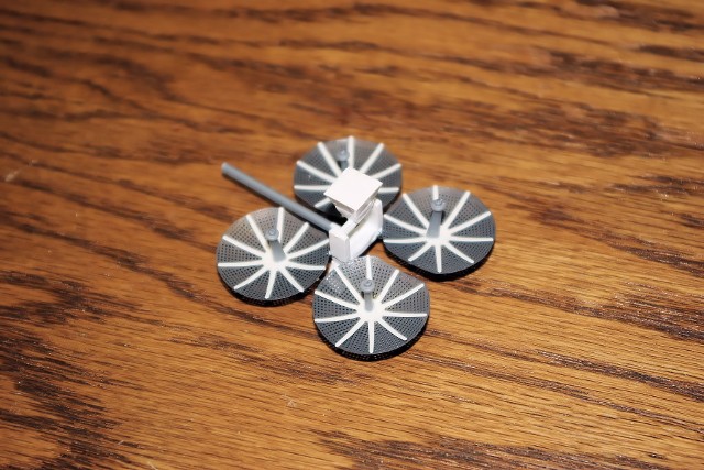
The dish assemblies were then fastened to the four posts of the support arm system, as indicated in the New Ware instructions. The four focus-point supports are then placed into position in the interior of the dishes. After the glue set, they are painted Flat White to match the spiders and the antenna complex support arm is painted aluminum.
Now, what about those fuel cells? I was just not happy with the way the label wrap looked on the top, so I decided to get some Web photos of the fuel cells and build-up some detail parts as necessary to do them right.
The upper section of the Pratt & Whitney Apollo fuel cells was a three-paneled arrangement placed on top of the pressure vessel and support canister.
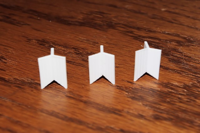
I fabricated these panel systems from 0.020 thick V-grooved styrene sheet, in order to add further surface detail to the panels. The parts used to replicate the fuel cell components were found by sifting through boxes of old surplus model parts and building others from sections of styrene tube and rod segments. The large valve body and the two solenoids on the back panels were made in this fashion.
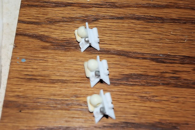
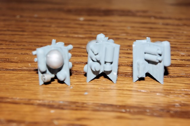
Once the parts were assembled onto the panels, painting was done to create further detail. Chrome Silver, Steel, Gunship Gray and Aluminum were used on the parts as directed by the photos of the real fuel cells, and the panels and canister bodies were done in Neutral Gray.
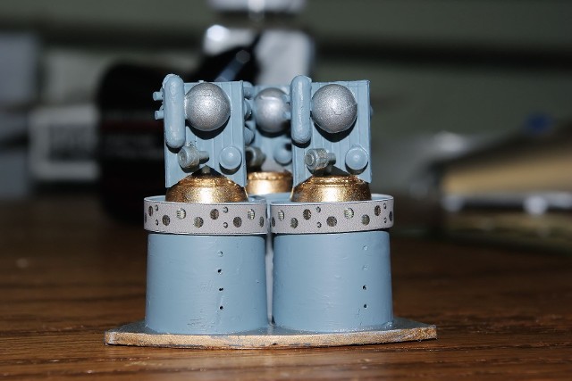
We did the “photo-realistic” thing to the P&W “nameplate” panel, which is on top of the connection system on the cell canister.
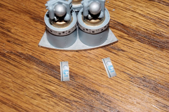
These labels were placed onto small sections of sheet styrene and placed onto the canister, immediately adjacent to the exits of the connected lines, which were formed from individual strands of copper wire.
They were terminated under a “connector plate,” which sits directly below an access hatch on the SM’s exterior skin.
With this assembly, I declared the Fuel Cells completed.
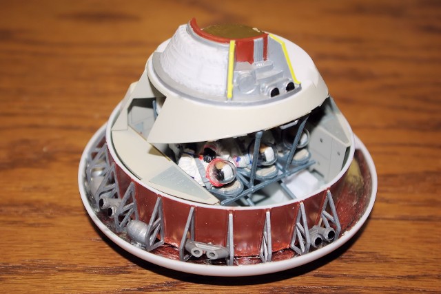
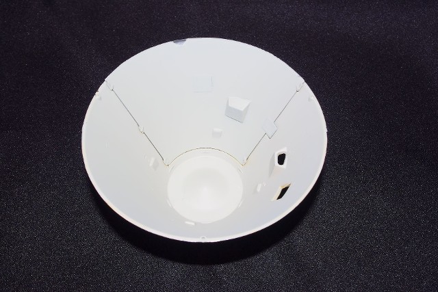
Command Module
We started with the structural interior of the CM, as indicated in the Monogram instructions. As Karl pointed out, the Zinc Chromate green reference in the model instructions is wrong and photographic research confirms that.
The interior surface of the heat shield dish was covered with silver foil to mimic the insulation foil and the structural ribs were painted aluminum. The exterior surface of the crew cabin base was painted in Rust (dark red) and the interior surfaces in Aircraft Gray, with the exception of the raised elements, which were painted white. The RCS units were installed in this view as well.
The nozzles for the Roll thrusters were extended to come out to the point where they will actually meet the CM skin and all RCS thrusters were painted in steel with black outlets. The RCS tanks were assembled. Their seams were sanded, they were painted aluminum and then mounted into their respective locations.
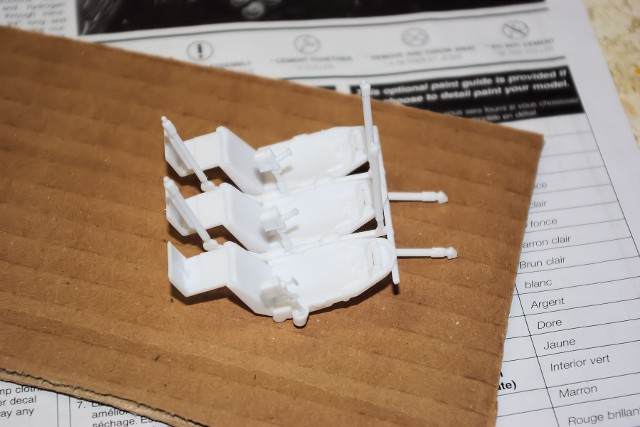
The crew couch assembly was done next. All of the parts of the couch system were cemented together and allowed to cure before further handling and painting.
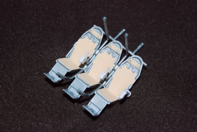
After glue drying, the frames of the couches were painted in “blue steel,” which is a mixture of Steel and Cobalt Blue, as recommended by Karl’s article. The pads and headrests of the couches are done in Sand color. The control boxes are Neutral Gray and the hand controllers are black.
The New Ware Interior Detail Set is essentially a group of PE parts, intended to be placed onto the surfaces of the existing interior panels in place of the decals furnished with the model. But, unlike the decals, these parts must be painted and hand detailed in order to get the most out of them. The primary color of the CM interior is Light Aircraft Grey. The “gray” sections specified by New Ware were done in Light Gray. Panel partition lines were highlighted by use of as fine point drafting pencil, which was also used to apply paint to very small, strategic areas.
This shows the three main perimeter walls of the crew cabin in place, with the New Ware detail supplements attached.
The forward section of the cabin contains the control console, which has numerous PE sections to attach. Follow the instructions and do detail painting very carefully.
The tunnel is a wrapped section of PE material, placed into the opening in the forward bulkhead. The forward hatch is attached to the top edge of the tunnel. Four additional detail parts are added to the inner surface of the tunnel.
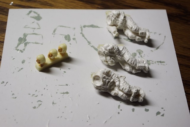
The three New Ware astronaut figures were started at this point. The suits of the three were painted in succeeding coats of gloss white, for better decal adhesion. For the “heads” of the crew, the faces were done in Flesh, and the “Snoopy Caps” received their flat black sides and flat white tops.
The seat belts, hose fittings, glove rings, gloves and helmet rings were added to the crew bodies, using the New Ware color recommendations.
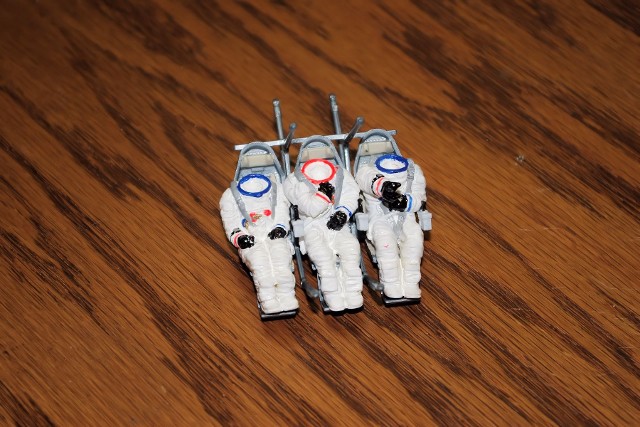
This was the first point where I had to “commit” the model to a particular flight, as the crew figures decals have flight insignias for only three Apollo missions – Apollo 8 (first flight around the Moon), 11 (first landing) and 17 (last flight of the lunar program). As I had not done a “J series” SM, with SIM bay detail, I could not use 17. Apollo 11 has been done dry. So I chose Apollo 8.
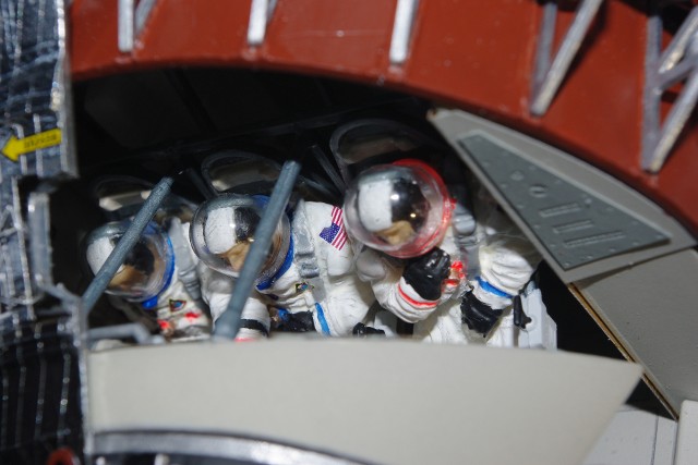
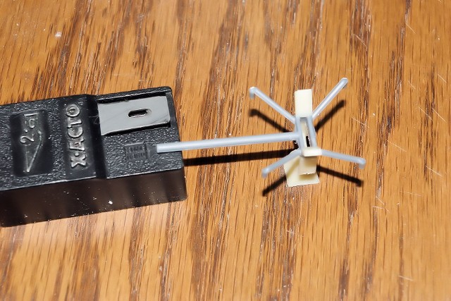
Because of the arm positions of the figures, only the LM pilot (right seat) and the CM Pilot (center seat) have exposed areas on their suits to support NASA “meatballs,” their last names and the flight patch. The seat belt location on the CM Pilot only should allow part of the flight patch to be seen, so the decal was placed over the belt, allowed to set, and then trimmed with a very sharp X-Acto knife. The Commander in the left seat has his hand over this area of the suit. The CM Pilot’s outstretched arm only allows this figure to be center seat – put him on either side and he won’t fit between the coach and the console. The vacuum formed “bubble helmets” fit well and are pretty nice looking as well.
After placing the crew into their couches, they were dull-coated by hand in order to seal the decals and lock the finish of their suits to a dull level, representing the “beta cloth” shell material. This also prevented accidental dull-coating of the bubble helmets.
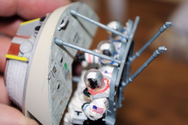
The combined crew/couch assembly was then fixed to the forward section with the control console system. Once dried, this assembly was fastened on to the top edges of the interior walls already located on the rear bulkhead. The lower couch system supports locate into the sockets provided in the cabin floor.
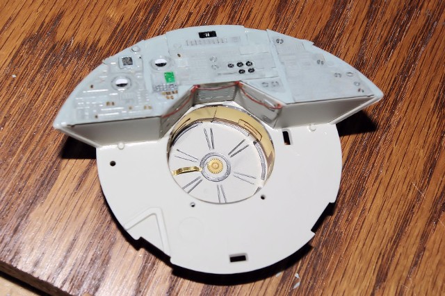
Then, the upper section showing the parachutes, tunnel section and RCS jets in located on the upper plane of the forward bulkhead. The painting details are found in Karl’s article in Space in Miniature.
The components of the Docking Probe were also removed from the runners, cleaned and assembled, so that painting of the probe in aluminum could be done prior to assembly onto the CM.
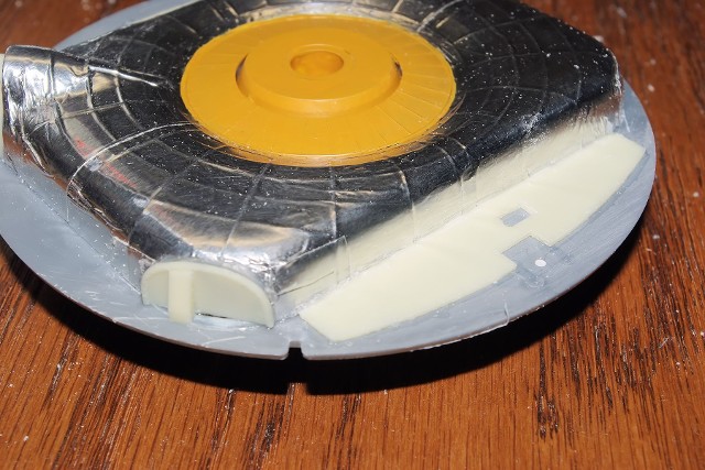
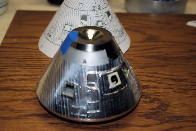
The outer hull sections, plated and clear, of the CM were held together with Painter’s Tape and the entire exterior surface was masked. The interior surface was masked where necessary and the surface was lightly “roughed up” with 400-grit sandpaper, in order to better hold a finish. Then, the entire interior surface was sprayed light Aircraft Gray.
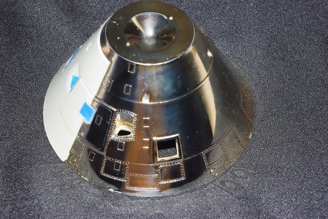
The exterior surfaces were unmasked and the clear yellow coating applied over the chrome plating of the main CM hull was removed using Isopropyl Alcohol, revealing the chrome plated surface below. Too bad Monogram did not mold the Mylar tape patterns into the surface of this part to begin with, but they didn’t. Now, the chrome plating will provide a base for the applied Bare Metal Film strips to come. The clear plastic section received a coat of Chrome Silver paint for it to be as close to the rest of the base surface as possible.
I found installing the side window and the forward Docking window of the major section of the CM hull after it was assembled onto the Heat Shield and interior would be very difficult, so I decided to mount them now prior to that phase. Testors Clear Window Cement was used here.
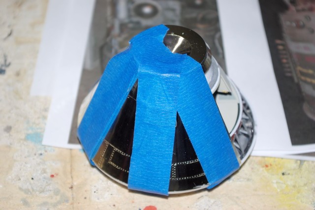
Once the windows were set, the primary hull section was trial fitted onto the top edge of the Heat Shield – interior assembly. I found that the molded locations for the Launch Escape Tower attachment points which extended inside the hull were preventing the section from sitting over the interior assembly properly, so they had to be shaved down using the Dremel tool, along with opening up the location slots on the forward bulkhead of the interior assembly. Blue painter’s tape was used to secure the parts while the cement set.
Now, we find that the “once-clear” removable section does not fit as we need it to fit, as it appeared to be curved at a slightly different radius than the main hull – Heat Shield assembly. When the hull was not fastened on the Heat Shield, like during the interior surface painting, they lined up great. Now that the other parts are involved, things are different. So we decided to try applying gentle, continuous heat to the panel, while it was secured to the rest of the system by tape to set the curve needed. You could use either a hair dryer or heat gun, set to a very low temperature, to prevent damage to the plastic.
In order to work the New Ware surface detail as well as the application of the BMF film strips, I decided to hold the removable section in place temporarily with small drops of ACC cement during the work. Hopefully, this will help get good alignment of the silver foil strip application, as well as promote a better overall panel fit.
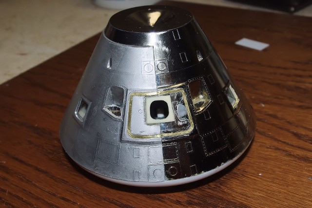
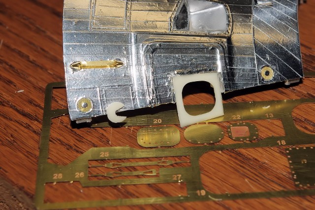
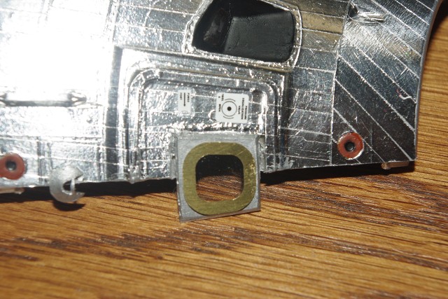
I first tried to apply the center window frame resin detail part onto the model, but found that the slight difference in height between the removable section and the hatch area of the prime hull to be too great. Therefore, the perimeter of the New Ware resin piece was marked on the removable section and using a narrow cutting wheel on the Dremel, we very carefully took the addition thickness down to allow the frame to rest flat from the removable section onto the surface of the main hull. This finally meant removing the “window” supplied on the clear section completely.
The frame was secured to the removable section only, so they can be parted. However, when the removable hull section is engaged, there will be no visible gap where the frame touches the main hull surface.
The window will be made of an “outer pane,” using the clear film placed between the PE and resin elements of the New Ware frame as indicated in their instructions. Then, a cylindrical inner element or “cell” has added, as is the case in the actual Apollo hatch. For now, we will leave all of this for assembly after all exterior finish work is completed.
The PE hatch detail “ring” was placed onto the locked surface and the seam location marked onto the part. Then, I very carefully cut the hatch ring with sheers, restored flatness at the ends, then located each half onto the respective hull section with ACC adhesive.
All of the other New Ware PE parts, such as the RCS jet rings and EVA handles, will wait for application until the BMF strips are applied.
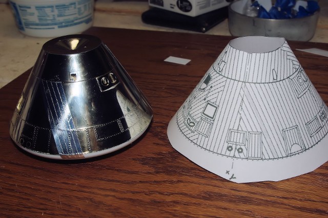
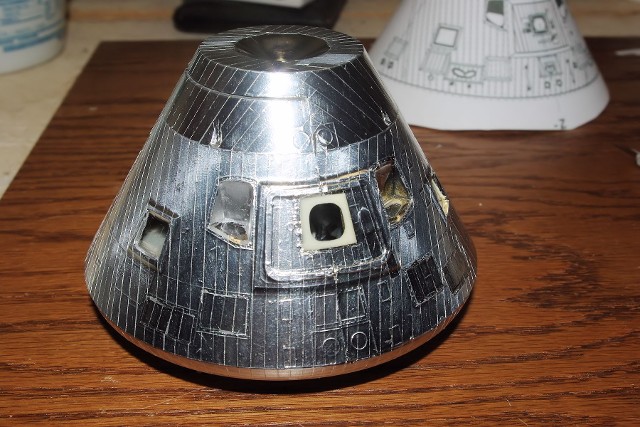
Within Space in Miniature Volume 6, there is a copy of the Mylar tape pattern from David Week’s Apollo drawing set. I scanned the image into my computer and using a graphic program, scaled a printout of the drawing so that the size matched the exterior surface of the 1/32 scale CM. The print was then cut-out and formed into the cone shape of the CM. This would be my template for executing the application of the BMF strips.
In order to this application scheme to work, the axis lines need to be placed onto the CM’s hull, so that the reference points of the drawing matched the work being done.
There’s a lot of careful trimming that must be done, at each edge and around objects on the CM’s surface. You will need a new, sharp #11 X-Acto blade during this process and use a very light touch. Read the BMF instructions for guidance.
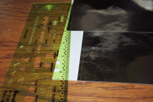
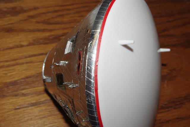
Each strip of BMF film was 6 mm wide, in order to best match the scale of the drawing. I sectioned off 3-1/2 long portions of the film to make the strips for the main body, which extends from the seam that runs around the top of the CM to the seam which is molded around the edge of the white aft heat shield. The strips wrap over the edge from the cone’s surface down to this seam line. This wrapped, curved area is obvious when looking at the two CMs on display in Florida and Washington. The 3-1/2 inch length allowed for all lower strips to be done with a minimum of waste.
I identified locations on the “tape map” “which could be easily repeated on the surface of the model as reference points to begin the application. Once those were placed, I just continued beyond them, one strip at a time, following the pattern of the map. It’s important to pay close attention to the locations where transitions occur, so that the strips match the pattern correctly. There is a “rhythm” to this pattern, and once you begin applying the strips, it becomes easier.
While this phase is tedious and time consuming, it is not difficult. The biggest challenge is the handling of the strips as they are removed from the backing paper. There is a natural tendency for the strips to “curl” as they come off, like Christmas ribbons. You must be very slow and deliberate when removing the film, making sure not to place all of the stress in a right-angle. A low-angled, slow release yields the best result.
Once the lower forward heat shield coverage was done, we moved to the upper forward heat shield section. There were again initial locations, right along the +Y and –Y axis lines, which run perpendicular to the seam line. These were our top reference points.
From there, you move across in both directions as the strips get a little longer and more angled with each application, until you reach the interface points at both the +X and –X axis. Once again, pay close attention to the map to see which strips take precedence at the axis line. The strips which occur before reaching the interfaces also cover the top edge of the CM and should be trimmed off and the inner hatch line.
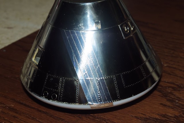
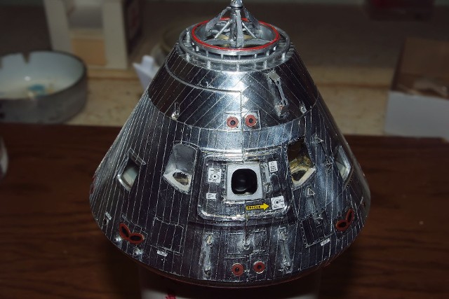
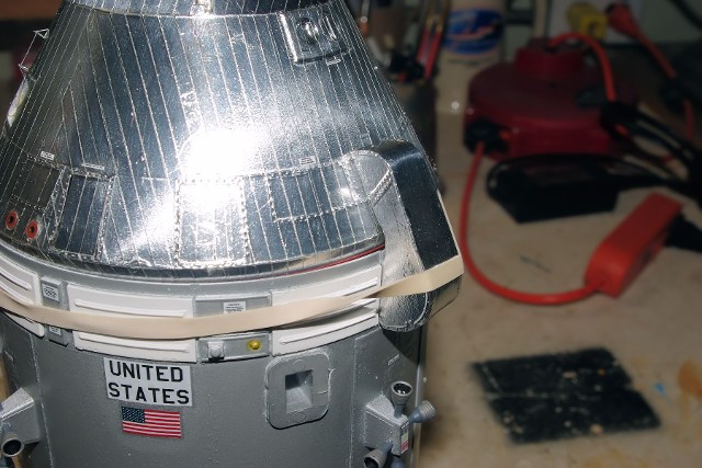
After four days of work, the entire CM surface was completed.
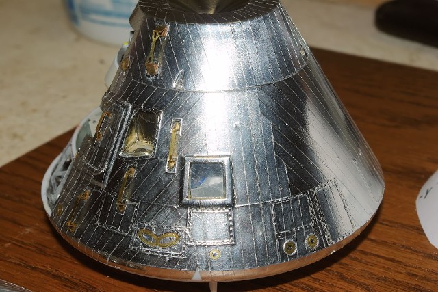
Now, it was time to apply the New Ware PE parts, such as the RCS jet rings, vent rings, and folded EVA handles and hatch handles. Fabrication of these handles is a delicate job, but again, not difficult. Take your time and read the New Ware manual carefully. Folded properly, these things look great.
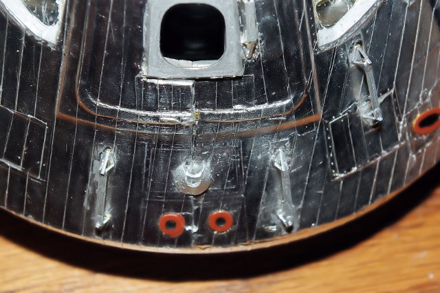
There are also two resin vent nozzles which are applied below the port side Roll jets, as well as the Sea Recovery Tether ring.
The ring was one of the most difficult items (for me) to work with, as the PE element was so small as to be virtually impossible to hold with a forceps, and the part would stick to the forceps magnetically and reorient itself at will. I found it easier to make a small plastic ring section form a slice of styrene tubing and place it into the opening of the ring base. The ring base then was cemented to the removable hull section only, as it must straddle the seam between fixed and removable hull sections.
All of the applied surface parts were painted as per New Ware’s instructions, as these colors were verified in NASA images of the Apollo CMs in flight.
The resin EVA handle ring was next mounted to the top of the CM. Special care must be taken to clean all excess resin from the part without damaging the part, as the ring is somewhat delicate.
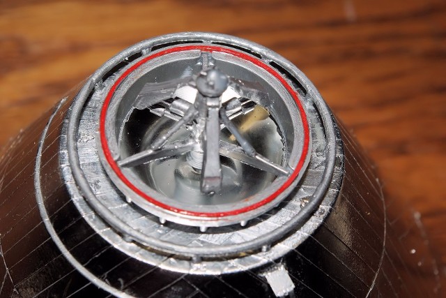
While the ring’s ACC is curing, you can work on the Docking Collar section of the CM’s tunnel. I painted the Red seal ring first, so that I could go back and do both the inner and outer edges of the upper portion in Chrome Silver, right up to the seal ring. The entire inside surface was painted Chrome Silver, as were the “legs” along the outside lower surface. The flat spaces between the legs were done in German Gray.
Once dried, the Docking Collar was mounted to top of the CM, using the two locator holes for alignment.
The New Ware CM exterior decals were placed onto the CM per the locations indicated.
A 1.5 mm wide line of red striping tape was run around the bottom-most edge of the BMF film / bottom heat shield interface to replicate the red ring on the actual Apollo CM
Once the decals had been set, the entire surface of the CM was inspected for any BMF film edge problems. The opening for the hatch window was masked on the inside, the removable hull panel was placed into the “closed” position and the entire exterior surface was sealed with gloss coat lacquer.
Once the gloss coat has completely dried, we painted the flat black lower angles of the Docking Windows and hand-brushed dull-coat lacquer over the RCS detail. This was easier than trying to mask off the items individually.
Now, we worked to complete the installation of the outer and inner hatch window elements.
The outer window was done as shown in the New Ware instructions, by taking a cut section of 0.010” thick clear sheet and cementing it to the back recessed edge of the PE outer frame.
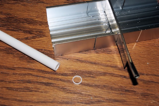
We then cut a 1/8” wide ring from 3/8” diameter styrene tube stock to fabricate the window cell.
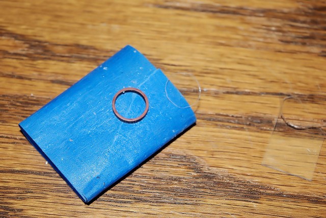
The ring was supported on blue Painter’s tape and given a coat of flat black. Once dry, the opposite edge was painted Rust (dark red), to create the window seal. A 3/8” diameter section of 0.010” clear sheet was cut out to become the inner window, and was cemented onto the red inner edge after the paint had dried.
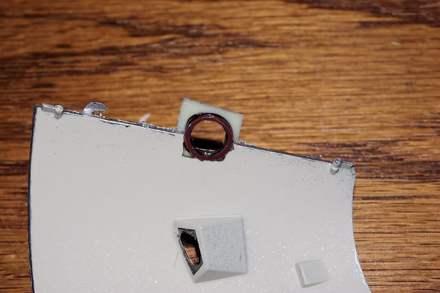
The completed assembly was then installed into the space where the original square window was removed during the outer resin frame installation.
The PE frame element with clear film was mounted on the exterior. The frame was painted Chrome Silver to match the resin and foil parts.
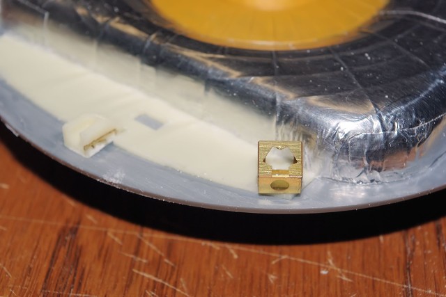
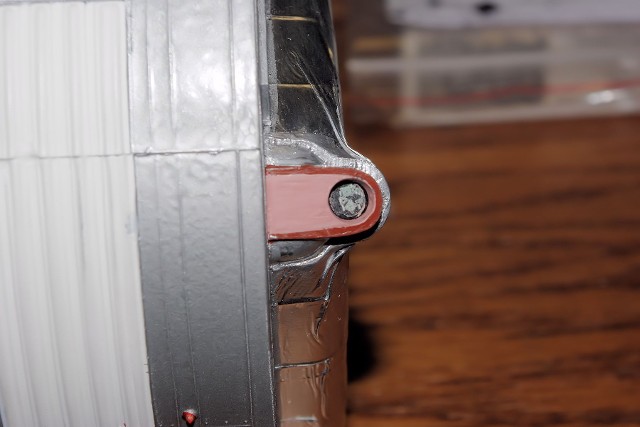
The New Ware cast Resin CM/SM umbilical housing was covered in Bare Metal Foil and test fitted to the mounting location on the SM. Because this part is solid and cannot be moved as the Monogram part did, we decided to lock the CM into position in its mounts on the SM forward bulkhead, then place and cement the Umbilical Housing onto both the SM and CM.
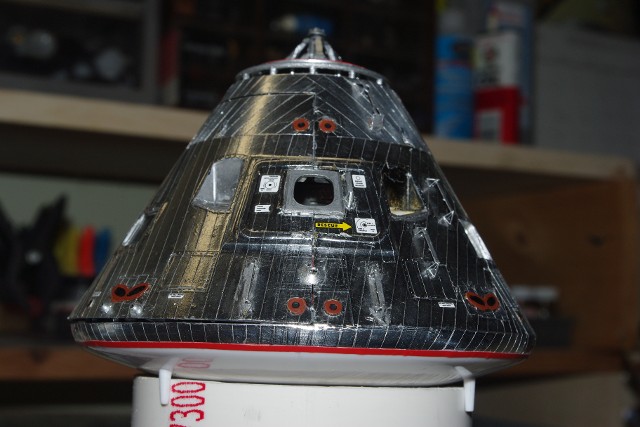
The last item was the placing of the CM’s VHF “omni” antennas onto the surface of the CM. As these are fitted into the skin, they were added as flat Neutral Gray semicircles to the proper locations on each side.
With the placement of the “omnis,” the detail upgrade 1/32 scale Apollo CSM is complete.
There are a number of potential approaches to display the model. Using the supplied Monogram stand is easiest, but my past experience with this model has shown that if steps are not taken to relieve the stress on the display stand’s mounting tab that inserts into the SM’s display socket, it will break off over time.
To remedy this, I placed a support “plate” onto the older display stand, which the rear edge of the SM rests upon, distributing the load.
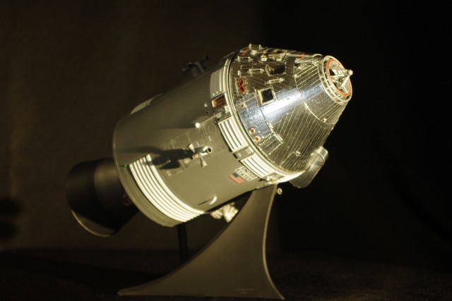
On the new model stand, this support role was accomplished by adding a section of 7/16” diameter styrene tubing, which also supports the rear of the SM, but is less visually obvious.
Both versions of the stand were sprayed Flat black. You can also choose to add markings, such as the Project Apollo insignia, if you want. Printing these onto self-adhesive label stock and applying them onto the stand is very simple to do.
Once again, my thanks go out to the following individuals and their works and products that made this build possible: Mike Mickowski & Karl Dodenhoff from Space in Miniature, Volume 6, Tomas Kladiva & staff at New Ware in the Czech Republic, John Duncan of the Apollo-Saturn Reference Pages, and the research staff of the Apollo-Maniacs web site.
 Lake County SpacePort